Amorphous Alloy Core Transformer Engineering Guide: Technical Evaluation, Total Cost of Ownership (TCO), and Global Procurement Trends

An in-depth analysis for electrical utility executives, EPC contractors, and grid modernization engineers. Discover how Fe-Si-B metallic glass core technology slashes no-load losses ($P_0$) by 70% to 80% compared to conventional CRGO steel, fulfilling modern Net-Zero carbon mandates and optimizing long-term lifecycle economics.

Contact Us Download Technical Dossier
70% - 80%
No-Load Loss ($P_0$) Reduction
Amorphous Ribbon Thickness
3 - 4 Yrs
Typical CapEx Payback Period
& IEEE C57 Fully Compliant

The Fundamental Physics of Amorphous Alloy Cores

In electric power distribution, grid operators face a continuous financial and environmental drain known as no-load loss (or iron loss, $P_0$). Unlike load loss ($P_k$), which varies with power consumption, no-load loss occurs 24 hours a day, 365 days a year, as long as the transformer remains energized. The Amorphous Alloy Core Transformer represents the single most effective technological leap in distribution transformer efficiency over the last half-century.

How Non-Crystalline Atomic Structures Eliminate Core Hysteresis

Conventional transformer cores utilize Cold-Rolled Grain-Oriented (CRGO) silicon steel. Despite advanced laser domain refining, CRGO retains a crystalline lattice structure. When subject to alternating magnetic fields (50/60 Hz), the domain walls inside CRGO repeatedly expand and contract, causing significant friction at the crystal grain boundaries—a phenomenon known as hysteresis loss.

Conversely, an amorphous alloy core (typically composed of Iron, Boron, and Silicon: Fe-Si-B) is manufactured via rapid solidification cooling at a rate of approximately $1,000,000 \, ^\circ\text{C}/\text{second}$. This extreme cooling prevents liquid atoms from forming a rigid crystalline lattice, producing a metallic glass foil only 0.025 mm (25 microns) thick—roughly one-tenth the thickness of standard 0.23 mm CRGO steel sheets.

Comparative Matrix: Amorphous Alloy (Fe-Si-B) vs. High-Permeability CRGO Steel

Physical Parameter Amorphous Alloy (Fe-Si-B) CRGO Steel (M0H / M1H Grade) Grid Operational Advantage
Atomic Lattice Amorphous (Non-crystalline) Crystalline (Grain-oriented) Eliminates domain boundary resistance
Lamination Thickness 0.025 mm (25 μm) 0.23 mm – 0.30 mm Massive reduction in Eddy Current Losses ($P_e \propto t^2$)
Core Loss at 1.3T / 50Hz ≤ 0.20 W/kg 0.85 – 0.95 W/kg 70% to 80% direct energy savings
Saturation Induction ($B_s$) 1.56 Tesla 2.03 Tesla Requires core design operating at $B_m \approx 1.30-1.35\text{T}$
Coercive Force ($H_c$) < 2.5 A/m ~ 8.0 A/m Easier magnetizing force requirement
Electrical Resistivity ($\rho$) 130 μΩ·cm 45 μΩ·cm 3x higher resistivity suppresses circulating currents

SOTEK Amorphous Core Transformer Flagship Line

Designed to comply with IEC 60076, IEEE C57, and EU EcoDesign Tier 2 / Stage 2 requirements. Engineered for power distribution utilities, solar energy step-up, and commercial installations.

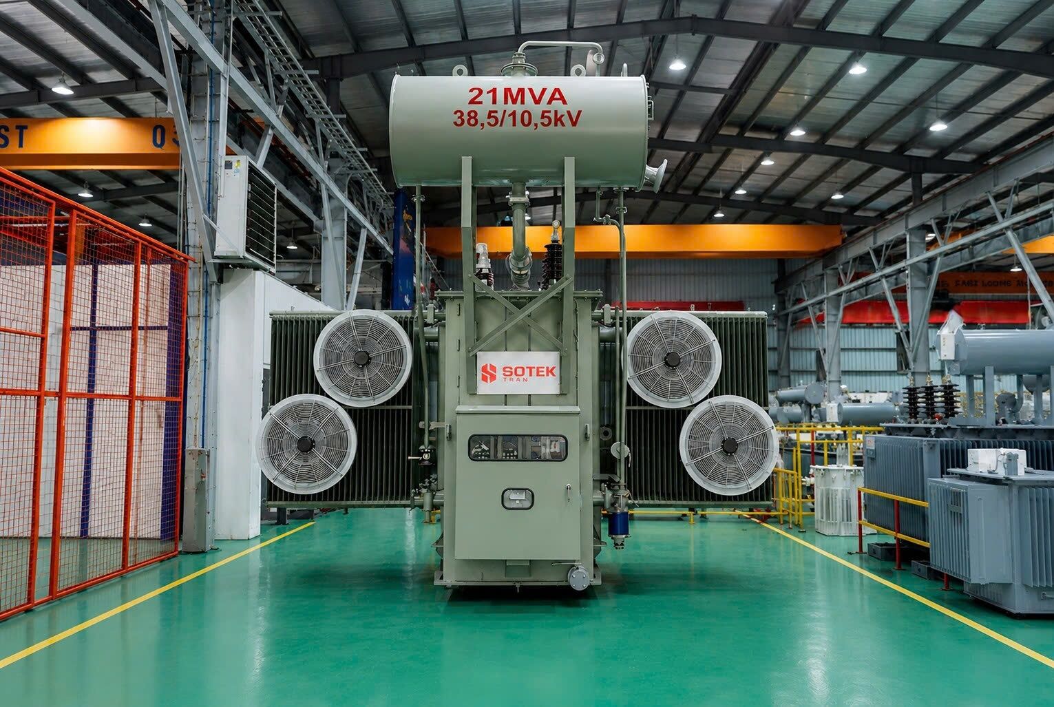
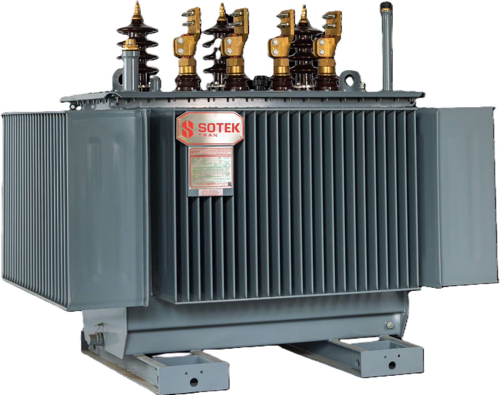
SOTEK Three-Phase Oil-Immersed Amorphous Alloy Core Distribution Transformer Top Grid Seller
Liquid-Filled · 50 kVA – 2,500 kVA

Three-Phase Oil Amorphous Transformer

Hermetically sealed corrugated tank design featuring high-permeability Fe-Si-B ribbon core. Provides maximum operational life in tropical, high-humidity, and heavy-duty utility networks.

50 – 2,500 kVA Up to 35 kV IEC 60076-20 ONAN / ONAF
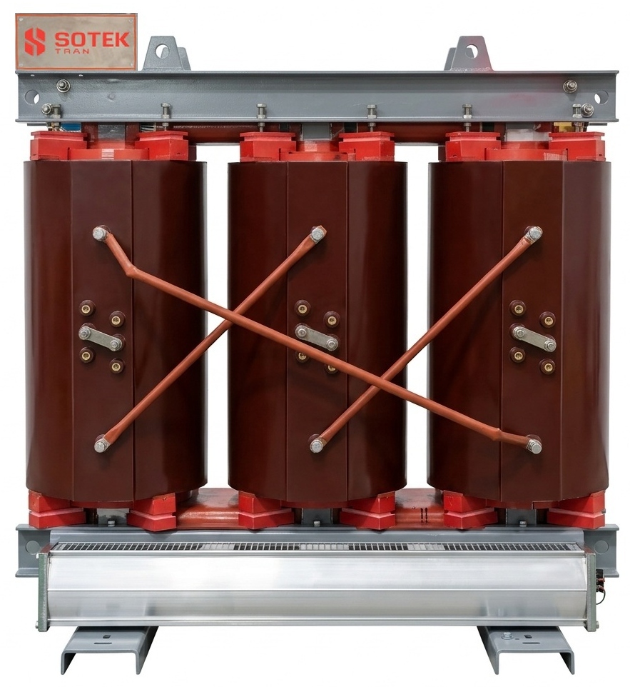
SOTEK Cast Resin Dry-Type Amorphous Core Transformer Indoor & Microgrid
Cast Resin · 100 kVA – 3,150 kVA

Cast Resin Dry-Type Amorphous Transformer

Vacuum pressure impregnated (VPI) or epoxy cast resin encapsulation. Self-extinguishing fire performance combined with ultra-low no-load loss for commercial towers, data centers, and underground substations.

100 – 3,150 kVA Class F / H IP20 – IP23 EcoDesign Tier 2
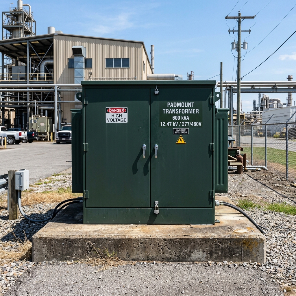
SOTEK Compartmentalized Amorphous Padmount Transformer IEEE C57 Underground Grid
Padmounted · 75 kVA – 3,000 kVA

Amorphous Alloy Padmount Transformer

Dead-front cabinet enclosure built strictly to IEEE C57.12.34 and ANSI C57.12.28 tamper-resistance standards. Available in both Loop-Feed and Radial-Feed configurations.

75 – 3,000 kVA IEEE C57.12.34 Dead-Front Bay-O-Net Fuse
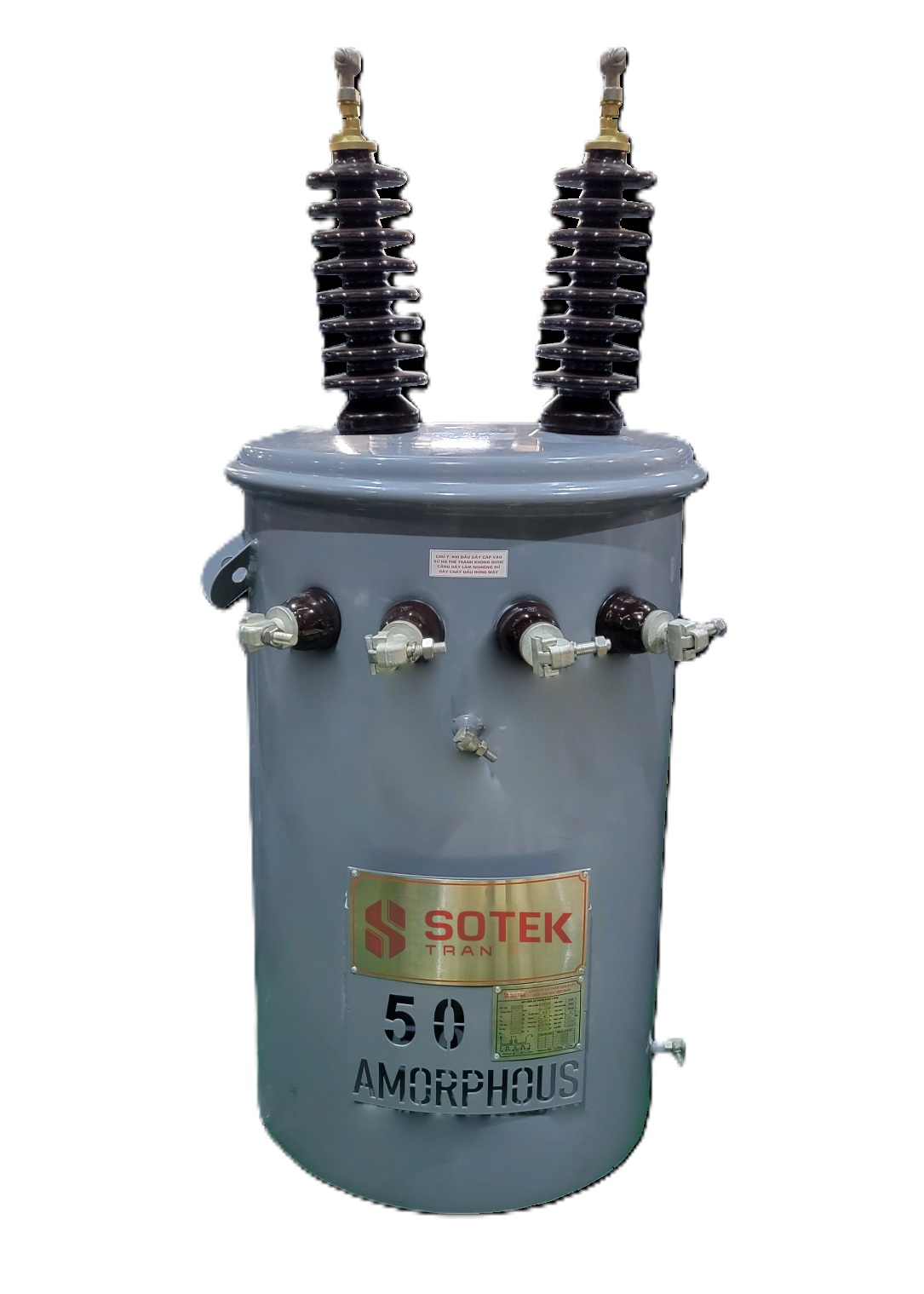
SOTEK Single-Phase Pole-Mounted Amorphous Core Transformer Rural Grid Specialist
Single-Phase Overhead · 15 kVA – 333 kVA

Single-Phase Overhead Amorphous Transformer

Lightweight overhead distribution units designed specifically for rural electrification projects with low load factors. Eliminates core energy waste during off-peak hours.

15 – 333 kVA Up to 34.5 kV ANSI C57.12.20 Rust-Resistant
SOTEK Solar and Wind Farm Step-Up Amorphous Substation Transformer Renewables Ready
Renewable Step-Up · Up to 5 MVA

Solar/Wind Step-Up Amorphous Transformer

Dual-winding or multi-winding inverter step-up transformer. Engineered to handle high harmonic distortion (K-Factor 13+) and variable load profiles in utility solar PV and wind sites.

Up to 5,000 kVA K-Factor Rated FR3 Natural Ester IEC / IEEE
SOTEK Industrial Compact Substation with Amorphous Transformer Core Integrated Package
Packaged Substation · 100 kVA – 2,500 kVA

Compact Kiosk Substation (Amorphous Core)

Factory-assembled outdoor substation containing MV Ring Main Unit (RMU), low-loss amorphous core transformer, and LV distribution panel inside a weather-proof metallic housing.

100 – 2,500 kVA IEC 62271-202 IP54 Enclosure Plug-and-Play

30-Year Total Cost of Ownership (TCO) Calculation

When evaluating distribution transformers, utility procurement teams frequently make the mistake of evaluating initial capital purchase price (CapEx) in isolation. However, electrical losses over a transformer’s 30-year operational lifespan typically represent 3 to 5 times the original purchase cost.

The Total Cost of Ownership (TCO) Standard Formula

$\text{TCO} = \text{CapEx} + (A \times P_0) + (B \times P_k)$

  • CapEx = Initial Purchase Price including logistics and installation.
  • $P_0$ = No-Load Loss (W), evaluated 8,760 hours/year regardless of loading.
  • $P_k$ = Load Loss (W) at rated current and reference temperature ($75^\circ\text{C}$).
  • A = Capitalized value of 1 Watt of No-Load Loss over lifetime ($\sim \$8.00 - \$12.00 / \text{W}$).
  • B = Capitalized value of 1 Watt of Load Loss based on load factor ($\sim \$1.50 - \$3.50 / \text{W}$).

Case Study: 1,000 kVA / 22 kV Utility Distribution Transformer

Consider a 1,000 kVA oil-immersed transformer installed in an urban network operating at an average load factor of 40%, with electricity cost at $\$0.12 / \text{kWh}$ over a 30-year lifecycle:

Performance Metric Standard CRGO Core Transformer SOTEK Amorphous Core Transformer Net Savings & Impact
No-Load Loss ($P_0$) 1,150 Watts 270 Watts 880 W Continuous Saving
Annual $P_0$ Energy Consumption 10,074 kWh / year 2,365 kWh / year 7,709 kWh / year Saved
30-Year No-Load Energy Cost $36,266 USD $8,514 USD $27,752 USD Direct Financial Gain
Lifetime CO2e Emissions 214.3 Tons CO2e 50.3 Tons CO2e 164.0 Tons CO2 Offset
Initial CapEx Premium Baseline ($0) + $2,800 USD CapEx Payback: 3.0 Years
Request Customized TCO Calculation for Your Grid

SOTEK Group: World-Class Transformer Manufacturing in Vietnam

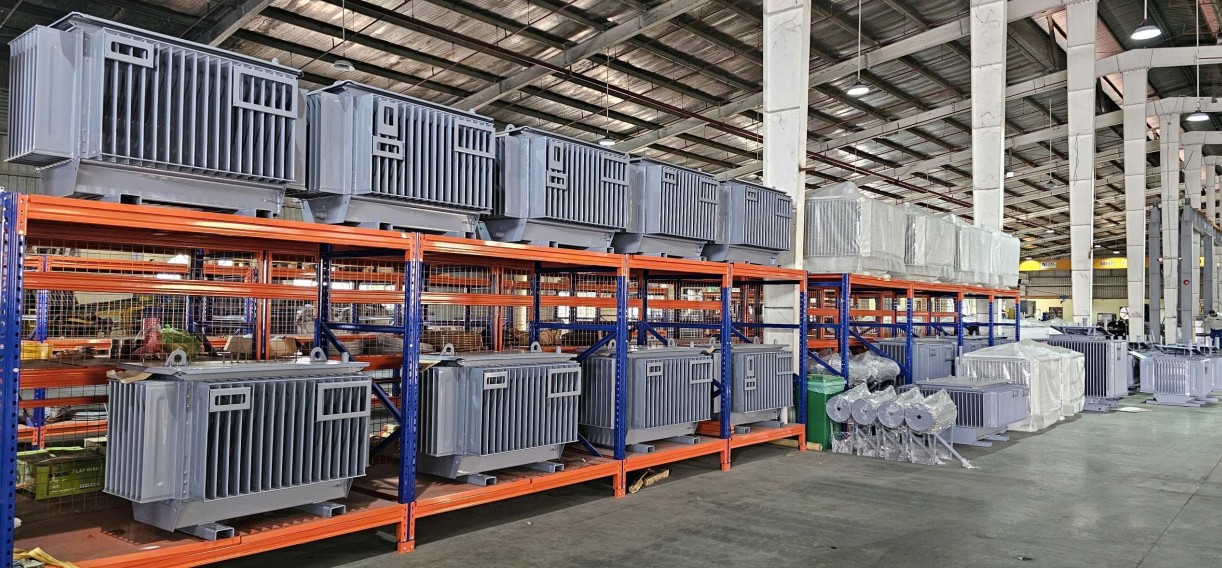
Established in 2008, SOTEK Group operates an advanced 18,500 m² primary manufacturing complex located in Tien Son Industrial Park, Bac Ninh Province, Vietnam. Dedicated strictly to electrical engineering precision, our plant integrates world-class machinery, including automated Georg core-cutting lines optimized for handling ultra-thin 0.025 mm amorphous ribbons without inducing structural micro-fractures.

Our facility features positive-pressure dust-free clean rooms, Hedrich automated vacuum casting chambers for cast resin transformers, and an ISO/IEC 17025 accredited high-voltage testing laboratory (VILAS 1183). SOTEK is an approved vendor for Vietnam Electricity (EVN) across all five regional distribution utilities, as well as international power players like Aboitiz Power.

18,500 m² Advanced Plant with Automated Georg (Germany) Core Lines
ISO 9001:2015, ISO 14001:2015 & ISO 45001 Certified System
In-House ISO/IEC 17025 (VILAS 1183) Accredited Type-Testing Bay
Proven Short-Circuit Withstand Capability per IEC 60076-5
Export Support to 30+ Nations with Complete FAT & CAD Dossiers
18,500 m²
Modern Vietnam Plant
GEORG
Precision Cutting Tech
VILAS 1183
ISO 17025 Accredited Lab
EVN & ABOITIZ
Approved Grid Vendor
IEC 60076
Full Compliance Certified
IEEE C57
North American Standard

Frequently Asked Questions by B2B Buyers & Utility Engineers

Clear, authoritative technical answers addressing common procurement inquiries regarding Amorphous Alloy Core Transformers.

Q1: How exactly does an amorphous alloy core transformer achieve 70% to 80% lower no-load loss compared to standard CRGO steel?

The dramatic reduction in no-load loss ($P_0$) stems directly from two material physics characteristics of Fe-Si-B metallic glass:
1) Absence of Crystalline Domain Boundaries: Because the molten alloy is cooled instantaneously ($\approx 10^6 \, ^\circ\text{C}/\text{sec}$), atoms do not align into a crystalline lattice. Magnetizing force does not encounter domain wall friction, reducing hysteresis loss by over 75%.
2) Ultra-Thin Lamination Foil: Amorphous ribbons are manufactured at just 0.025 mm (25 microns) thickness compared to 0.23 mm – 0.30 mm for CRGO steel. Since eddy current loss is proportional to the square of lamination thickness ($P_e \propto t^2$), eddy losses become virtually negligible.

Q2: Are amorphous metal core transformers more susceptible to short-circuit mechanical forces?

Amorphous ribbon material exhibits high mechanical hardness but lower tensile elasticity compared to CRGO steel. To counteract electromagnetic radial and axial forces during grid short circuits ($I_{sc}$), SOTEK utilizes a specialized rectangular coil structure with reinforced epoxy-resin core support frames. The amorphous core is supported inside a rigid steel frame box without bearing the physical weight of the windings. SOTEK amorphous transformers are fully type-tested and certified to withstand short-circuit stresses under IEC 60076-5 and IEEE C57.12.90.

Q3: Is an amorphous core transformer noisy? How does SOTEK address magnetostriction noise?

Amorphous metal possesses a higher magnetostriction coefficient than CRGO steel, which can lead to elevated audible hum if unmitigated. SOTEK resolves this through three proprietary design parameters: (1) Operating at an optimized flux density design point ($B_m \approx 1.30\text{T} - 1.35\text{T}$, well below the 1.56T saturation point), (2) Applying sound-dampening resin coatings across core lap joints, and (3) Utilizing acoustic isolation dampers within the tank assembly. As a result, SOTEK amorphous transformers strictly meet or beat standard NEMA ST-20 and IEC sound level requirements.

Q4: What is the typical financial payback period (CapEx vs. OpEx) when upgrading to an amorphous transformer?

While an amorphous core transformer carries a CapEx premium of approximately 15% to 30% over standard CRGO units due to core manufacturing complexity, the dramatic reduction in continuous no-load energy drain typically yields a full return on investment (ROI payback) within 2.5 to 4.0 years depending on local commercial electricity tariffs. Over a 30-year operational life, the transformer generates net cumulative savings equal to several times its initial purchase cost.

Q5: What technical documentation and certifications are provided with SOTEK export shipments?

Every SOTEK transformer batch ships with a comprehensive technical dossier certified by our ISO/IEC 17025 accredited laboratory (VILAS 1183). Documentation includes Routine Test Reports (winding resistance, voltage ratio, phase displacement, no-load loss & current, load loss & impedance, applied AC voltage, induced overvoltage), Type Test Reports (Lightning Impulse Test, Temperature Rise Test), CAD outline drawings, material mill certificates, and Certificate of Origin (Form E/Form AK/Form B).

Q6: How does SOTEK handle OEM customization and lead times for overseas utility contracts?

SOTEK maintains a dedicated international engineering desk to adapt designs to buyer specifications (e.g., dual HV ratings, special tap ranges with OLTC/DETC, IEEE padmount dead-front configurations, FR3 natural ester fluid options). Standard lead times range between 4 to 8 weeks depending on kVA sizing and batch volume. Containerized sea freight is managed directly from Hai Phong Port (Vietnam) with full FOB, CIF, or DDP Incoterms support.

Ready to Reduce Your Grid Losses with Amorphous Core Technology?

Contact SOTEK’s senior engineering team today for technical specifications, custom CAD designs, competitive factory-direct pricing, and lifetime TCO evaluations.

Contact Us Email Direct Engineering Query