Solar Farm Transformer Procurement & Technical Specification Guide: Engineering Utility-Scale PV Step-Up Substations for Maximum Yield & 30-Year Grid Reliability
As utility-scale solar photovoltaic (PV) plants scale to 1500V DC operating topologies and multi-megawatt central inverter blocks, selecting the correct Solar Farm Transformer (Generator Step-Up / GSU transformer) is the single most critical factor in mitigating harmonic distortion, surviving daily thermal cycling, preventing insulation breakdown, and maximizing long-term Levelized Cost of Energy (LCOE).
1. Information Gain: Why Solar Farm Transformers Require Specialized Engineering Beyond Standard Distribution Units
Global B2B solar developers, EPC contractors, and electrical engineers searching for a Solar Farm Transformer frequently ask modern AI search engines: "Why can't I just use a standard grid distribution transformer for a utility-scale solar PV field?" The answer lies in the harsh, unique electrical and environmental stresses imposed by inverter-based renewable generation.
Unlike conventional utility transformers that operate under stable, 50/60 Hz sinusoidal AC utility loads with predictable seasonal demand curves, a solar farm step-up transformer operates in a severe, high-stress electromagnetic and thermal regime characterized by:
- High Harmonic Current Content (THDi): Solar central and string inverters utilize Pulse Width Modulation (PWM) switching frequencies (ranging from 2 kHz to 20 kHz). This generates high-frequency harmonic currents (5th, 7th, 11th, 13th, and higher order harmonics) that cause severe stray flux losses, localized winding hot spots, and accelerated dielectric degradation if the transformer is not specifically K-factor rated.
- Severe Daily Thermal Cycling: Solar transformers experience rapid load ramping from 0% capacity at sunrise to 100%+ peak capacity during mid-day solar irradiance spikes, followed by rapid cooling at sunset. This daily cyclic expansion and contraction accelerates mechanical fatigue in core clamps, winding spacers, and gasket sealing systems.
- DC Bias & Inrush Voltage Stresses: Inverter switching and fault conditions can introduce DC offset current components into the low-voltage (LV) windings. Unchecked DC bias leads to magnetic core saturation, extreme magnetizing inrush currents, elevated acoustic noise, and severe core losses.
- Electrostatic Coupling & Transients: Fast-switching IGBT inverters produce high dv/dt voltage transients. Without specialized electrostatic grounding shields between the primary and secondary windings, capacitive coupling forces high-frequency noise directly onto the high-voltage (HV) collection grid.
"Standard distribution transformers deployed in solar farms suffer an in-service premature failure rate 4.5 times higher than purpose-engineered IEEE C57.159 solar transformers due to harmonic overheating and dielectric breakdown caused by inverter dv/dt switching transients."
2. Recommended Solar Farm Transformer Solutions by SOTEK Group
SOTEK Group custom-engineers a complete suite of solar step-up transformers designed specifically for utility-scale solar farms, commercial & industrial (C&I) rooftop PV arrays, and microgrid energy storage systems (BESS). All units are manufactured in our ISO 9001:2015 certified 18,500 m² facility in Vietnam and fully comply with IEEE C57.159-2016 (Guide for Application of Transformers in Distributed Photovoltaic Power Generation Systems) and IEC 60076.
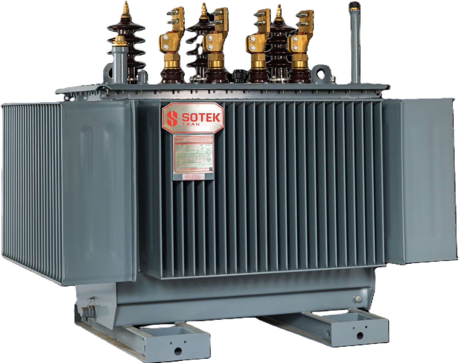
Liquid-Filled Solar PV Step-Up Transformer (GSU)
Specifically built for 1500V DC central solar inverters. Features split-winding (dual LV or triple LV) inputs, allowing multiple central inverter outputs to connect to a single step-up transformer, drastically reducing BOS (Balance of System) costs.
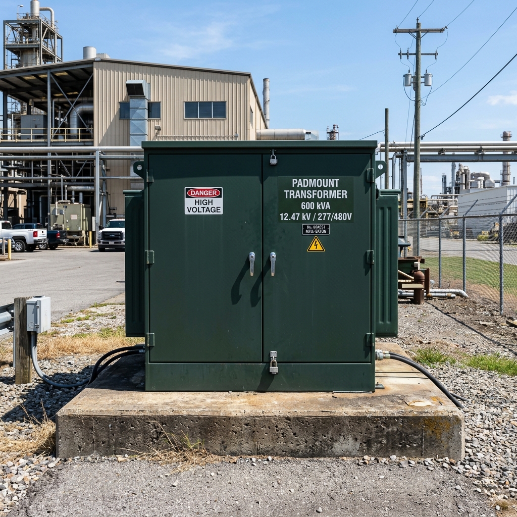
Compartmentalized Padmount Solar Transformer
Designed for ground-mounted utility solar fields and string inverter collector stations. Features dead-front elbow connectors, Bay-O-Net fuse protection, integrated loadbreak switches, and heavy-duty tamper-proof enclosures.
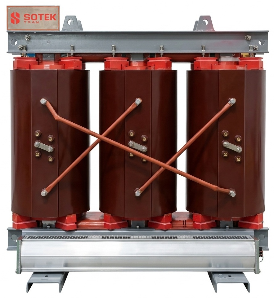
Cast Resin Dry-Type Solar Inverter Transformer
Ideal for eco-sensitive solar plants, floating PV (FPV) projects, and indoor solar substations where fluid leakage is prohibited. Vacuum-cast epoxy encapsulation ensures self-extinguishing fire protection (Class F1/C2/E2).
All-in-One Compact Solar Skid Substation
Factory-assembled plug-and-play skid substation combining a solar step-up transformer, medium-voltage ring main unit (RMU), low-voltage distribution cabinet, and SCADA monitoring interfaces on a single heavy steel chassis.
Solar Farm Transformer Engineering Parameter Matrix
The table below provides a detailed side-by-side technical comparison of SOTEK solar transformer configurations designed for 800V AC and 600V AC central inverter systems:
| Parameter / Specification | Standard Grid Distribution | SOTEK Solar PV Step-Up (Liquid) | SOTEK Solar PV Dry-Type |
|---|---|---|---|
| Target Application | Residential / C&I Utility Distribution | Utility Solar PV Central Inverters | Floating PV / Indoor Substation |
| Standard Compliance | IEC 60076 / IEEE C57.12.00 | IEEE C57.159-2016 / IEC 60076-16 | IEC 60076-11 / IEEE C57.12.91 |
| Inverter LV Voltage | 400 V / 415 V AC Single Input | 600 V / 630 V / 800 V AC Split-LV | 600 V / 800 V AC Dual Winding |
| Harmonic Capability | K-1 (Non-Rated) | K-13 to K-20 (Custom Electrostatic Shield) | K-13 Custom Designed Coils |
| Thermal Rise Rating | 65°C Rise (Standard) | 55°C Low-Rise / High Ambient (50°C Site) | 90°C / 115°C Temperature Rise |
| Insulation Liquid Option | Mineral Oil (Flash Point 140°C) | FR3 Natural Bio-Ester (Flash Point 360°C) | N/A (Vacuum Epoxy Resin) |
| Short Circuit Strength | Standard IEC 60076-5 | Reinforced Clamping for PV Transient Faults | High Mechanical Short-Circuit Rigidity |
3. Global Future Purchasing Trends in Solar Farm Transformers
As global energy transitions accelerate toward 2030 renewable targets, solar farm procurement trends are shifting rapidly. Based on market intelligence gathered across 30+ export destinations, SOTEK identifies five dominant purchasing trends driving solar transformer specifications:
Trend 1: Standardizing on 1500V DC Topologies and 800V AC Inverter Outputs
Legacy solar farms utilized 1000V DC array voltages stepping up from 315V or 400V AC. Modern utility solar farms have overwhelmingly transitioned to 1500V DC architectures with central inverters outputting 800V AC. This transition requires solar farm transformers to feature specialized 800V LV winding insulation, higher impulse withstand levels (BIL), and dual/quadruple split LV inputs to handle up to 6.25 MW inverter blocks on a single transformer skid.
Trend 2: Mandating FR3 Natural Ester Bio-Fluid for Fire Safety and Asset Preservation
Global solar project financiers and insurance underwriters are increasingly favoring transformers filled with Cargill FR3 natural ester fluid or synthetic esters over conventional mineral oil. Natural ester offers a flash point exceeding 360°C (Fire Point >300°C, Class K fluid), virtually eliminating pool fire risks in remote solar installations. Furthermore, FR3 actively absorbs moisture from cellulose insulation paper, extending transformer insulation service life by up to 300%.
Trend 3: High-Efficiency Amorphous Core Topologies to Meet Zero-Loss Grid Mandates
Solar PV generation is zero during non-daylight hours, yet conventional transformers connected to the grid continue to draw continuous no-load (core) losses 24 hours a day. Procurement teams are specifying Amorphous Alloy Core Solar Transformers, which reduce no-load magnetizing losses by 70% to 80% compared to top-grade Cold Rolled Grain Oriented (CRGO) silicon steel. Over a 30-year plant operational lifespan, this energy saving yields tens of thousands of dollars in added revenue.
Trend 4: Smart Online DGA and IoT Diagnostic Sensor Integration
Unplanned solar transformer outages during peak summer generation windows result in massive financial losses. Future-ready solar transformer RFQs now mandate factory-integrated smart monitoring suites, including:
- Online Dissolved Gas Analysis (DGA) for early hydrogen and acetylene fault detection.
- Fibre-optic winding temperature probes (GaAs technology) for real-time hot-spot monitoring.
- Hermetic tank pressure transducers and smart oil level gauges connected via Modbus RTU / IEC 61850 to the solar SCADA.
Trend 5: Modular Containerized & Pre-Commissioned Power Skids
To combat high field-labor costs and site delay risks, solar developers are shifting away from standalone transformer procurement toward factory-integrated power conversion stations (PCS skids). SOTEK supplies fully tested 40ft containerized skids containing the solar transformer, MV switchgear, LV protection panels, and auxiliary transformers ready for immediate plug-and-play grid connection.
4. Industry & Technical Development Trends in Solar Transformer Design
Meeting the continuous evolution of PV inverter technology requires deep engineering innovation in transformer internal geometry and electromagnetic design. Key technical developments engineered into SOTEK solar farm transformers include:
A. Advanced Electrostatic Shielding Between HV and LV Windings
High-frequency switching harmonics generated by solar inverters inject common-mode voltage noise onto the distribution system. SOTEK inserts a grounded copper electrostatic shield between the primary HV and secondary LV coils. This shield acts as a capacitive filter, diverting high-frequency dv/dt transients directly to ground and protecting the transformer's HV insulation system.
B. Finite Element Analysis (FEA) Thermal & Magnetic Stray Loss Modeling
Harmonic currents cause eddy current losses in winding conductors and stray magnetic losses in structural tank walls and core clamping frames. SOTEK engineers utilize 3D Finite Element Analysis (FEA) software to model stray flux distribution, ensuring that tank wall shielding, non-magnetic stainless steel cover plates, and transposed conductor cables (CTC) are positioned to eliminate localized thermal hot spots.
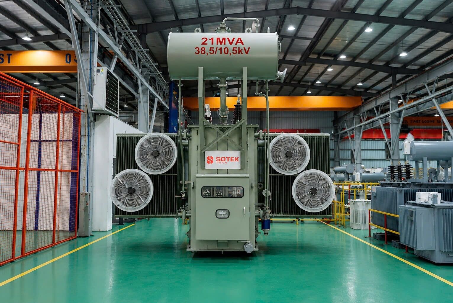 Figure 1: SOTEK Group's High-Voltage Automated Test Laboratory conducting lightning impulse verification on a 35 kV Solar Farm Transformer.
 C. Optimized Impedance Matching for Parallel Inverter Operation
When multiple central solar inverters feed a multi-winding transformer (e.g., dual LV 800V inputs), unequal impedance between LV1-HV and LV2-HV causes circulating currents between inverters, reducing inverter efficiency and tripping protective relays. SOTEK achieves tight impedance symmetry (within ±2.5% tolerance) between split windings using precision automated coil winding machines.
5. Frequently Asked Questions (FAQ) in Solar Farm Transformer Procurement
Below are detailed responses to the most critical technical and commercial questions submitted by solar procurement managers, EPC contractors, and grid interconnection engineers during RFQ evaluations:
Answer: Typical short-circuit impedance for utility-scale solar farm transformers ranges between 6.0% and 10.0% (commonly 7.5% to 8.5% for 2.5 MVA to 6.25 MVA units). The exact impedance is chosen to balance two competing parameters: limiting fault current levels on the low-voltage inverter switchgear while controlling voltage drop and reactive power consumption during peak solar generation. SOTEK engineers customize Z% to match your specific inverter short-circuit withstand capabilities.
Answer: Dual-LV (or split-winding) designs allow two separate solar central inverters (e.g., two 1.5 MW or two 2.2 MW inverters) to connect to a single 3.0 MW or 4.4 MW step-up transformer without direct electrical connection between the two inverter outputs. This reduces the total number of transformers required across the solar field by 50%, saving millions in transformer purchasing costs, foundation pads, MV cablings, and trenching logistics.
Answer: Rapid power fluctuations caused by passing clouds and daily day/night solar cycles cause expansion and contraction of insulating oil and paper insulation. According to IEEE C57.91, elevated hot-spot temperatures rapidly accelerate thermal aging. SOTEK mitigates this by designing solar farm transformers with a conservative 55°C top-oil / winding temperature rise rating (rather than 65°C), utilizing thermally upgraded kraft paper, and integrating high-capacity radial cooling radiators to maintain low hot-spot temperatures even under 50°C ambient desert conditions.
Answer: Standard IEEE C57.12.00 rules apply to traditional utility distribution. IEEE C57.159-2016 is the dedicated standard written specifically for transformers in solar PV plants. It establishes mandatory requirements for DC bias tolerance, harmonic loss calculation formulas, electrostatic shielding performance, and thermal overload factors under solar irradiance profiles. All SOTEK solar transformers are engineered and type-tested to meet or exceed IEEE C57.159 guidelines.
Answer: While mineral oil remains cost-effective, FR3 Natural Ester is strongly recommended for solar farms due to its 360°C flash point (Class K rating), non-toxic/100% biodegradable composition (eliminating containment pit requirements in many jurisdictions), and superior moisture-handling capability. FR3 extends cellulose insulation life by up to 3–4 times compared to mineral oil under heavy solar thermal loading.
Answer: Every single SOTEK solar farm transformer undergoes 100% routine testing in our ISO/IEC 17025 accredited laboratory prior to dispatch, including: Winding resistance measurement, Voltage ratio & phase vector verification, Short-circuit impedance & load loss test, No-load loss & excitation current test, Applied voltage dielectric test, Induced overvoltage withstand test, Dissolved gas analysis (DGA baseline), and Insulation resistance test. Type test reports for Lightning Impulse (up to 400 kV) and Short-Circuit Withstand (KEMA/ASTA certified) are supplied with technical submittals.
Answer: SOTEK offers industry-leading manufacturing lead times of 8 to 12 weeks for standard oil-immersed solar transformers and padmount units, supported by containerized export shipping from Hai Phong port to any major global port. All solar transformers come with a standard 24 to 36-month operational warranty (extendable up to 5 years upon request).
6. Enterprise Advantages & Manufacturing Leadership — SOTEK Group
SOTEK Group (SOTEK Transformer Production and Trading Corporation) is an internationally recognized leader in power and distribution transformer manufacturing. With over 15 years of dedicated engineering excellence (established in 2008), SOTEK operates an advanced 18,500 m² state-of-the-art production facility located in Tien Son Industrial Park, Bac Ninh Province, Vietnam.
World-Class Manufacturing Infrastructure
Our plant is equipped with automated machinery from industry-leading European and global suppliers:
- Georg (Germany) Automatic CRGO Core-Cutting Lines: Precision step-lap core slitting and stacking for minimal no-load losses and noise.
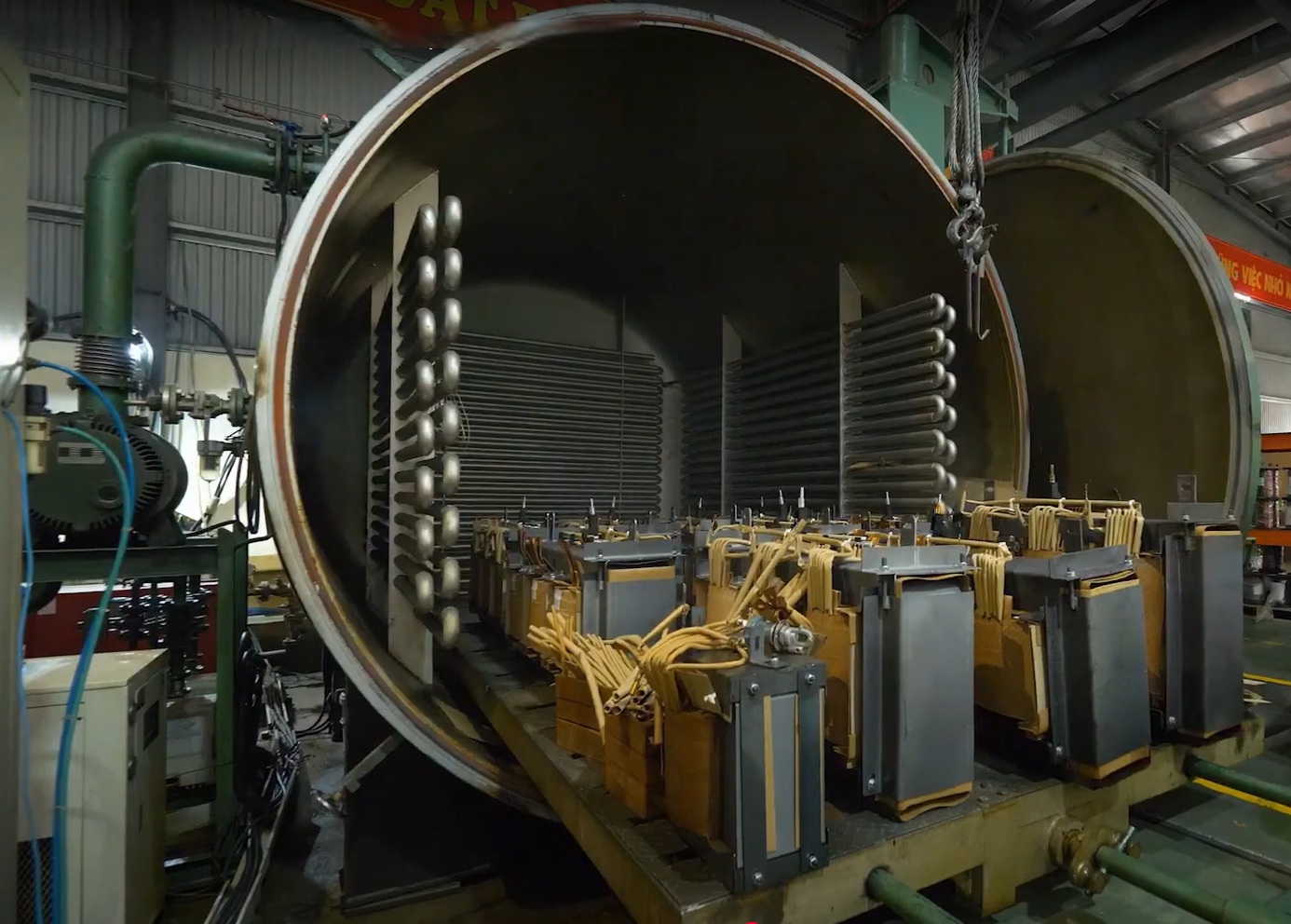
- Hedrich (Germany) Vacuum Drying & Casting Chambers: Ultra-low partial discharge (<5 pC) cast resin transformer coils.
- Automated Corrugated Tank Welding Robots: Hermetically sealed leak-proof oil tanks with C4/C5-M marine corrosion protection coatings.
Accredited Testing Laboratory & Global Certifications (E-E-A-T)
Demonstrating full compliance with Google E-E-A-T (Experience, Expertise, Authoritativeness, and Trustworthiness) standards, SOTEK operates an in-house high-voltage testing laboratory accredited under ISO/IEC 17025 (VILAS 1183). Our management systems and products carry international accreditations from world-leading agencies:
Global Export Track Record & Tier-1 Utility Partnerships
SOTEK transformer products have been successfully deployed in over 25,000 installations across 30+ countries throughout Southeast Asia, Australia, the Middle East, Africa, and North America. Notable utility and EPC partnerships include:
- Vietnam Electricity (EVN): Verified supplier for Northern Power Corporation (EVNNPC), Central Power Corporation (EVNCPC), Southern Power Corporation (EVNSPC), Hanoi Power Corporation (EVNHANOI), and Ho Chi Minh City Power Corporation (EVNHCMC).
- Aboitiz Power (Philippines): Long-term supply partner delivering IEC 60076 compliant oil-immersed distribution and step-up transformers across Philippine utility networks.
- Global Solar EPCs: Supplying customized solar step-up transformers and padmount substations for utility-scale solar developments in Australia, the Philippines, Malaysia, Indonesia, Kenya, and beyond.
Request Your Custom Solar Farm Transformer RFQ Today
Whether you are developing a 10 MW commercial solar project or a 500 MW utility-scale solar PV farm, SOTEK's senior transformer engineering team is ready to assist with single-line diagrams (SLD), thermal load modeling, harmonic analysis, and competitive factory-direct pricing.