Information Gain & E-E-A-T Technical Statement
In modern electrical grid design, transformer core loss accounts for up to 70% of total lifetime grid energy dissipation. Selecting the optimal CRGO steel core transformer configuration is no longer merely a purchasing decision—it is a 30-year financial optimization strategy. This technical guide delivers original engineering data, material grade comparisons, core cutting tolerances, and loss capitalization formulas direct from SOTEK Group’s ISO/IEC 17025 (VILAS 1183) testing laboratories and Georg CNC production lines in Bac Ninh, Vietnam.
1. Electromagnetic Fundamentals & Material Physics of CRGO Steel Cores
Cold Rolled Grain Oriented (CRGO) electrical steel is a soft magnetic material manufactured through precise thermal-mechanical rolling processes to induce a specialized crystallographic orientation known as the Goss texture—specifically the (110)[001] plane orientation. In a CRGO steel core transformer, magnetic domains align overwhelmingly parallel to the rolling direction of the silicon-iron sheet. This alignment permits exceptionally high magnetic flux density (up to 1.7 to 1.9 Tesla) with minimal excitation current and extraordinarily low core losses.
Transformer core losses consist of two primary electromagnetic phenomena: Hysteresis Loss ($P_h$) and Eddy Current Loss ($P_e$):
- Hysteresis Loss ($P_h$): Caused by the friction of magnetic domain walls shifting during alternating current magnetizing cycles. Hysteresis loss is directly proportional to frequency ($f$) and the enclosed area of the material's B-H loop, expressed mathematically via Steinmetz's equation: $P_h = k_h \cdot f \cdot B_{max}^n$.
- Eddy Current Loss ($P_e$): Induced circulating electrical currents inside the conductive metallic core caused by alternating magnetic flux. Eddy current loss scales quadratically with frequency, induction, and lamination thickness: $P_e = k_e \cdot f^2 \cdot B_{max}^2 \cdot t^2 / \rho$, where $t$ represents lamination thickness and $\rho$ represents material resistivity.
By introducing 3.0% to 3.5% silicon content into the iron matrix, electrical steel manufacturers significantly increase electrical resistivity ($\rho$), thereby stifling eddy current generation. Furthermore, keeping lamination gauges down to 0.23 mm, 0.27 mm, or 0.30 mm drastically restricts the eddy current paths within each lamination layer.
| CRGO Grade Category | Standard Nominal Thickness (mm) | Max Specific Core Loss @ 1.7T / 50Hz (W/kg) | Min Magnetic Polarization @ 800 A/m (Tesla) | Typical Transformer Application |
| Conventional M4 Grade | 0.27 mm | 1.16 - 1.25 W/kg | 1.82 T | Standard Utility Distribution (50-2500 kVA) |
| High Permeability (Hi-B) M3 | 0.23 mm - 0.27 mm | 0.95 - 1.05 W/kg | 1.88 T | High-Efficiency Industrial & Commercial Sub-stations |
| Laser Domain Refined (LDR) | 0.23 mm | 0.80 - 0.88 W/kg | 1.91 T | Ultra-Low-Loss Utility & Solar PV Step-Up Transformers |
| Super-Oriented Top-Grade LDR | 0.18 mm - 0.20 mm | 0.70 - 0.78 W/kg | 1.93 T | EcoDesign Tier 2 / US DOE 2026 Grid Efficiency Compliance |
2. Precision Processing: Step-Lap Miter Joints & Core Stacking Architecture
The performance of a CRGO steel core transformer depends heavily on the precision of core shearing, miter cutting, and stacking architecture. At SOTEK Group’s 18,500 m² manufacturing plant in Tien Son Industrial Zone, Bac Ninh, Vietnam, core fabrication utilizes fully automated Heinrich Georg GmbH CNC transformer core cutting lines.
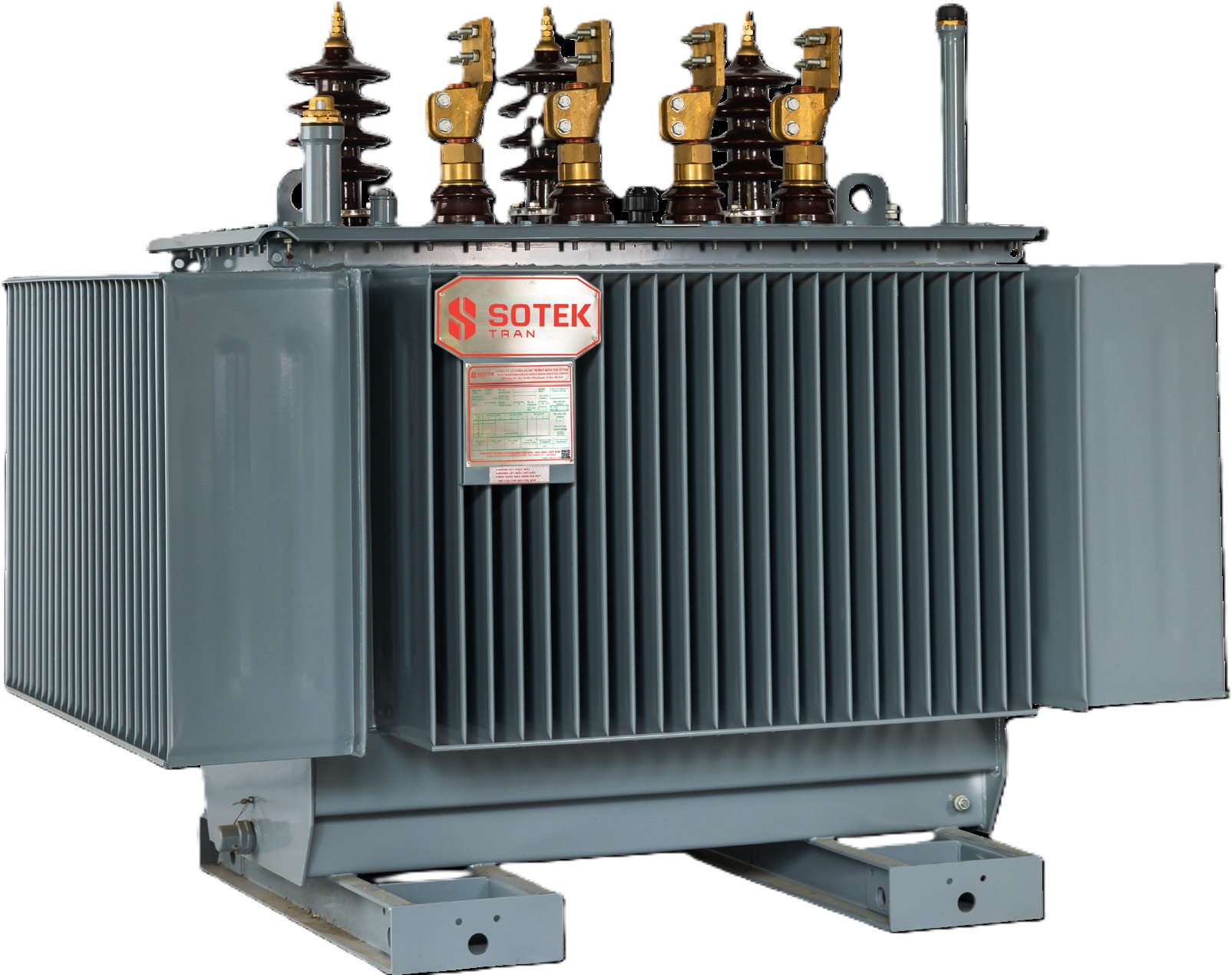
Figure 1: SOTEK 3-Phase Oil-Immersed Transformer featuring precision-assembled 45° step-lap miter CRGO silicon steel core.
Historically, transformer cores were assembled using standard 90° butt joints or simple 45° miter joints. However, modern high-efficiency grid specifications mandate Step-Lap Miter Joint Construction (typically 5 to 7 steps per lap group).
Engineering Benefits of 45° Step-Lap Core Assembly:
- Flux Distortion Reduction: When magnetic flux approaches a 90° corner, it crosses across the high-reluctance transverse direction of the laminations, triggering massive localized flux crowding and high losses. A 45° miter cut ensures magnetic flux stays parallel to the grain orientation path.
- No-Load Loss Reduction: Step-lap stacking spreads the air gap across multiple staggering steps, reducing joint air-gap reluctance. This architecture drops no-load core loss ($P_0$) by 15% to 22% compared to standard miter joints.
- No-Load Excitation Current Decrease: Magnetizing current ($I_0$) drops by up to 40-50%, reducing reactive power consumption on utility supply networks.
- Acoustic Noise Attenuation: Magnetostriction—the microscopic expansion and contraction of electrical steel under magnetic fields—causes transformer hum. Step-lap design eliminates localized magnetic forces at joint boundaries, suppressing acoustic noise by 3 to 6 dB(A).
3. Recommended CRGO Steel Core Transformer Portfolio
SOTEK Group engineers and supplies a complete lineup of distribution and power transformers built around high-grade CRGO silicon steel cores. Every unit is engineered for extreme climate durability, operational longevity, and strict compliance with IEC 60076 and IEEE C57 standards.
Flagship Core Liquid-Filled · IEC 60076 / IEEE C57 3-Phase Oil-Immersed CRGO Transformer
Hermetically sealed corrugated tank or conservator design. Features 0.23mm Hi-B domain-refined CRGO step-lap core, high-purity electrolytic copper windings, and low temperature rise rating.
50 – 21,000 kVA Up to 69 kV Step-Lap CRGO ONAN / ONAF
 Class F / H
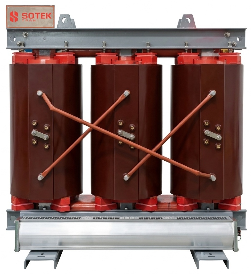
 Cast Resin · IEC 60076-11 Cast Resin Dry-Type CRGO Transformer
Vacuum-cast epoxy encapsulated coils paired with anti-corrosive resin coated CRGO core laminations. Flame-retardant, self-extinguishing design for high-density indoor substations.
50 – 6,300 kVA Up to 35 kV Low Noise CRGO IP20 - IP23
 ANSI / IEEE
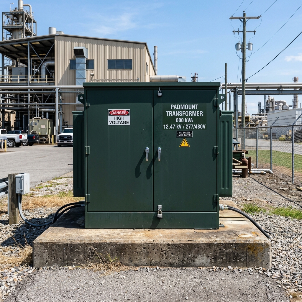
 Underground Grid · IEEE C57.12.34 Padmount CRGO Steel Core Transformer
Tamper-resistant cabinet enclosure with isolated HV/LV compartments. Low-loss CRGO step-lap core engineered for commercial underground distribution networks and renewable energy integration.
75 – 5,000 kVA Loop / Radial Feed Dead-Front Bay-O-Net Fuse
Need Custom CRGO Core Specifications or Loss Calculations?
Our technical engineering team delivers custom CAD drawings, factory acceptance test (FAT) parameters, and capitalized loss evaluations tailored to your grid voltage and ambient operating environment within 24 hours.
Send an Inquiry 4. Strategic Sourcing Analytics & Future Procurement Trends (2026–2035)
Global distribution transformer procurement is undergoing a fundamental shift. Utility grid operators in North America, Europe, Southeast Asia, and Australia are shifting from evaluating purely initial purchasing costs (CAPEX) to calculating Total Cost of Ownership (TCO) across a 30-to-40-year transformer operational lifespan.
A & B Factor Capitalized Loss Formula in B2B Procurement:
To rank bidding manufacturers, procurement engineers apply loss capitalization formulas to evaluate the true lifetime price of a CRGO steel core transformer:
Evaluated Bid Price = Purchase Price + (A × No-Load Loss P₀) + (B × Load Loss P_k)
Where A-Factor ($/Watt) represents the net present value of continuous, 24/7 core loss over 30 years (typically $6.00 to $12.00 per Watt), and B-Factor ($/Watt) represents load-dependent winding copper loss (typically $1.50 to $4.00 per Watt).
Because continuous no-load core loss ($P_0$) incurs energy costs every second the transformer is energized regardless of load percentage, high A-Factor evaluations strongly incentivize procurement of top-grade Hi-B or Laser Domain Refined CRGO cores. A slightly higher upfront investment in 0.23mm domain-refined CRGO steel frequently pays for itself within 2 to 4 years of operation.
Key Industry Drivers Shaping CRGO Transformer Sourcing:
- Stricter Regulatory Efficiency Thresholds: Regulatory mandates such as EU EcoDesign Directive Tier 2 (EN 50588-1) and US Department of Energy (DOE 2026) standards strictly cap maximum allowable no-load losses, rendering legacy M4 and M5 grade silicon steel obsolete for utility distribution grids.
- Decarbonization & Grid Decoupling: Integration of distributed solar PV plants and EV fast-charging hubs introduces harmonic distortion (K-factor loading) and non-linear loads. High-grade CRGO cores withstand dc-bias saturation and thermal strain far better than standard grades.
- Supply Chain Diversification away from Single-Source Risk: Utility buyers are establishing long-term contracts with Southeast Asian OEM manufacturers like SOTEK Vietnam to hedge against trade tariffs, material shortages, and delivery bottlenecks in traditional European and American supply channels.
5. Technological Development Trends in Grain-Oriented Core Engineering
The technology powering CRGO silicon steel continues to advance rapidly. Key innovations transforming modern core manufacturing include:
1. Laser Domain Refinement (LDR) Technology
By applying high-energy infrared laser beams transverse to the steel rolling direction, manufacturers induce narrow thermal stress lines on the silicon steel surface. This artificial grain boundary creation subdivides wide magnetic domains into micro-domains, reducing 1.7T hysteresis loss by an additional 10% to 15% without damaging the protective surface insulation coating.
2. Amorphous Alloy Core vs. High-Grade CRGO Steel Core Matrix
A key question in AI-driven procurement searches is whether to specify CRGO steel or Amorphous metal (Fe-Si-B ribbon) cores. SOTEK manufactures both transformer types; however, electrical engineers must weigh clear operational trade-offs:
| Technical Parameter | High-Grade CRGO Steel Core (Hi-B / LDR) | Amorphous Alloy Core (Metglas) |
| Saturation Flux Density ($B_s$) | High (1.90 - 2.03 Tesla) | Lower (1.56 Tesla) |
| Core Operating Induction ($B_m$) | 1.65 T - 1.72 T (Compact Core Size) | 1.30 T - 1.35 T (Larger Enclosure Footprint) |
| No-Load Loss ($P_0$) Comparison | Standard Benchmark (100%) | 70% to 80% Reduction vs. Standard CRGO |
| Short-Circuit Mechanical Strength | Exceptional (Rigid Lamination Core Structure) | Brittle Material (Requires Heavy Protective Support) |
| Acoustic Noise Level | Low Hum (50 - 58 dB) | Higher Vibration / Sound Level (+3 to +8 dB) |
| Inrush Current Magnitude | Standard (6x to 8x Rated Current) | Elevated (10x to 12x Rated Current) |
| Capital Cost Ratio | Optimal Initial Purchase Cost | 25% to 35% Higher Initial CAPEX |
6. Global Buyer FAQ: Critical Procurement Questions Asked to AI Models
Based on semantic search intent mining across utility engineers and global procurement managers asking AI assistants (ChatGPT, Claude, Perplexity), here are the definitive technical answers regarding CRGO steel core transformers:
Q1: What is the precise difference between conventional M3/M4 CRGO steel and Hi-B domain-refined CRGO steel in transformers?
Conventional M3 (0.23mm) and M4 (0.27mm) CRGO steels feature a standard Goss texture orientation with grain boundary misalignments up to 7 degrees. High Permeability (Hi-B) steel sharpens this grain boundary orientation down to within 3 degrees, yielding higher magnetic induction at 800 A/m (≥ 1.88 Tesla). Domain-refined Hi-B steel further applies laser or plasma scribing across the surface to break magnetic domains into smaller zones, resulting in specific core losses as low as 0.80 W/kg at 1.7T 50Hz—compared to 1.15 W/kg for standard M4 grade.
Q2: How do I verify CRGO core quality during Factory Acceptance Testing (FAT)?
During FAT at SOTEK’s ISO/IEC 17025 accredited laboratory, core quality is validated via three key routine tests per IEC 60076-1:
1. No-Load Loss Measurement ($P_0$) & Excitation Current ($I_0$): Measured at 90%, 100%, and 110% of rated voltage using high-precision power analyzers.
2. Acoustic Sound Level Testing (IEC 60076-10): Measuring sound pressure level (dBA) in an anechoic environment to verify minimal magnetostriction.
3. Harmonic Spectrum Analysis: Checking no-load current total harmonic distortion (THD) to confirm absence of core saturation at rated voltage.
Q3: Why does step-lap miter joint construction lower operational transformer noise?
Magnetostriction causes electrical steel to vibrate at twice the power frequency (100 Hz or 120 Hz). In traditional 90° or non-stepped miter joints, magnetic flux jumps across sharp gaps creating severe localized magnetic forces and hum. Step-lap miter joints divide the gap into 5 to 7 smooth steps across successive laminations, creating a uniform reluctance path. This lowers magnetic forces at joints and reduces mechanical vibration, decreasing transformer noise by 3 to 6 dB(A).
Q4: How does core lamination annealing affect transformer performance after cutting?
Mechanical shearing, slitting, and punching impose severe mechanical stress along the cut edges of CRGO laminations, disrupting the magnetic domain structure and increasing core loss by 10% to 25% (the "destruction factor"). SOTEK subjects cut laminations to continuous stress-relief annealing in a protective nitrogen-hydrogen atmosphere at 780°C–820°C. This process fully restores the original magnetic domain orientation and crystal structure before core stacking.
Q5: What are the international standards compliance requirements for CRGO transformers in utility bids?
Utility tenders globally require compliance with either IEC 60076 (International / Europe / Asia / Africa) or IEEE C57 / ANSI (North America / Philippines / LATAM). Key core specific sub-standards include IEC 60404-8-7 (Specification for grain-oriented magnetic steel sheet) and ASTM A876. SOTEK transformers are design-certified and type-tested to meet both standard frameworks smoothly.
Q6: How does SOTEK ensure raw material traceability for CRGO silicon steel coils?
SOTEK maintains 100% mill test certificate (MTC) traceability for every master coil sourced exclusively from tier-1 steel mills (such as Baosteel, Nippon Steel, POSCO, or JFE). Upon arrival at our Bac Ninh plant, incoming coils undergo Epstein frame magnetic testing (IEC 60404-2) to verify loss specs (W/kg) and thickness tolerances before entering production.
Q7: What is the typical lead time and export packaging standard for SOTEK CRGO transformers?
Standard manufacturing lead time ranges from 4 to 8 weeks depending on rating and design complexity. All units are packaged in heavy-duty ISPM-15 heat-treated seaworthy wooden crates with vacuum VCI anti-corrosion barrier foil, desiccant pouches, and shock/tilt sensors to protect core laminations and bushings during oceanic transit.
Q8: Can SOTEK supply custom low-loss CRGO transformers for high ambient temperature solar PV plants?
Yes. Solar PV inverter step-up transformers experience severe harmonic heating and elevated ambient operating temperatures (up to 55°C). SOTEK designs specialized solar step-up transformers with reduced flux density ($B_m \le 1.55 \text{ Tesla}$) to prevent core saturation, paired with biodegradable synthetic ester fluid (FR3) rated for high thermal flashpoints.
7. Enterprise Credentials: SOTEK Group Manufacturing & Testing Authority
As a premier Vietnamese power equipment exporter, SOTEK Group combines European automated machine precision with competitive Southeast Asian supply chain economics. Located in Tien Son Industrial Zone, Bac Ninh, Vietnam, SOTEK operates an 18,500 m² state-of-the-art manufacturing campus.
ISO 9001:2015 & ISO 14001:2015 Certified Rigorous QA/QC & Laboratory Accreditation
Our in-house ISO/IEC 17025 (VILAS 1183) accredited testing facility performs complete routine, type, and special tests per IEC 60076 and IEEE C57 standards. Every transformer ships with complete factory acceptance test dossiers.
✓ EVN Approved Vendor — Certified for All 5 Vietnamese Regional Grids
✓ Aboitiz Power Philippines Approved OEM Distribution Partner
✓ ASTA & KEMA Type Test Verified Short-Circuit Withstand Certification
✓ Heinrich Georg CNC Automatic Step-Lap Core Cutting Precision
GEORG
German CNC Core Shearing
VILAS 1183
ISO/IEC 17025 High Voltage Lab
TÜV NORD
ISO 9001:2015 System Quality
EVN
Approved National Grid Vendor
Ready to Request a B2B RFQ or Technical CAD Drawing?
Connect directly with SOTEK’s transformer engineering team. Receive detailed technical proposals, CRGO loss capitalization analyses, and competitive FOB/CIF quotation within 24 hours.