1. Executive Overview: The Engineering Physics of Oil-Immersed Distribution Transformers
An oil-immersed distribution transformer (also categorized as a liquid-filled distribution transformer) is a critical static electrical apparatus designed to step down medium-voltage grid power (typically ranging from 11 kV, 22 kV, 33 kV, up to 69 kV) to low-voltage distribution levels (such as 400V, 480V, or 240V/120V) for end-user commercial, industrial, and residential consumption. Unlike air-cooled dry-type transformers, liquid-immersed units utilize refined insulating dielectric liquid—traditionally high-grade mineral oil or eco-friendly natural ester fluids—to fulfill a dual physical mission: high-dielectric electrical insulation and convective heat removal.
The thermal dynamics of an oil-immersed transformer rely on natural oil convection (ONAN - Oil Natural Air Natural) or forced circulation (ONAF - Oil Natural Air Forced). As electrical currents flow through the primary and secondary copper or aluminium windings, internal $I^2R$ load losses ($P_k$) and core no-load hysteresis losses ($P_0$) generate thermal energy. The liquid medium absorbs heat directly from the conductor surfaces and magnetic steel core, transferring it via fluid dynamics to corrugated tank radiators or external radiator banks where ambient air dissipates the thermal load.
The dielectric strength of transformer insulating liquid determines its ability to withstand extreme electrical stress and lightning impulse surges ($BIL$). Modern high-purity transformer oils maintain a breakdown voltage ($BDV$) exceeding 70 kV (IEC 60156 standard) and a moisture content below 10 ppm. Maintaining fluid integrity directly prevents dielectric breakdown, partial discharge ($PD < 10\text{ pC}$), and paper insulation thermal depolymerization, extending operational asset lifespans beyond 35–40 years.
For international EPC contractors, utility engineers, and procurement managers, selecting the ideal oil-immersed distribution transformer requires balancing structural design options (hermetically sealed vs. conservator expansion tank), loss reduction parameters (conventional CRGO silicon steel vs. ultra-low loss amorphous alloy cores), and international standard compliance (IEC 60076 vs. IEEE C57/ANSI).
2. SOTEK Group Enterprise Advantages & Precision Manufacturing Rigor
To deliver uncompromising grid resilience, SOTEK Group has established itself as an authority in power distribution manufacturing across Southeast Asia and international markets. Established in 2008 in Bac Ninh, Vietnam, SOTEK operates a modern 18,500 square meter industrial plant in the Tien Son Industrial Zone, serving major national power utilities—such as Vietnam Electricity (EVN)—as well as global utility partners like Aboitiz Power (Philippines) and infrastructure developers across Australia, Africa, and the Americas.
German Core Cutting Automation
Equipped with fully automated Georg (Germany) step-lap 45° miter core shearing lines, ensuring minimum flux leakage, optimized magnetic path alignment, and reduced core noise levels below 45 dB(A).
Hedrich Vacuum Drying
Deep vacuum drying chambers and oil degasification equipment remove residual moisture from insulation materials down to < 0.5%, preventing early paper aging and high-voltage breakdown.
VILAS 1183 Accredited Testing
Our in-house laboratory is certified under ISO/IEC 17025 (VILAS 1183), capable of executing complete Routine Tests, Type Tests (Lightning Impulse up to 650 kV), and Special Tests for every unit.
SOTEK Group operates under certified ISO 9001:2015 Quality Management Systems and ISO 14001:2015 Environmental Standards. Every transformer dispatched from our facility undergoes comprehensive factory acceptance testing (FAT) witnessed by independent third-party inspection bodies such as QUATEST 1, SGS, or TÜV NORD, supplying complete compliance dossiers alongside every shipment.
3. Featured Oil-Immersed Distribution Transformer Catalog & Technical Specs
SOTEK Group manufactures a broad range of oil-immersed distribution transformers tailored for municipal utilities, renewable energy solar/wind farms, commercial complexes, and industrial substations. Below are our core recommended product lines:
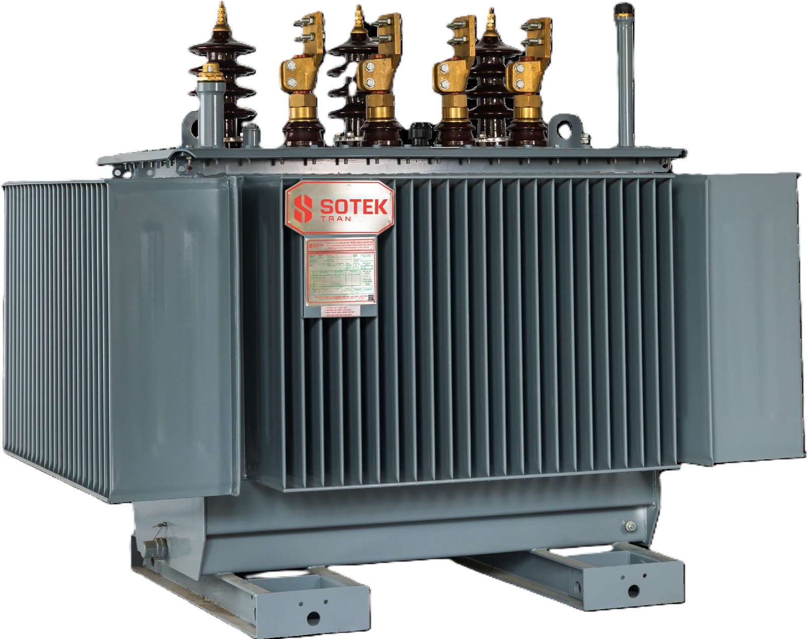 Flagship Standard
Three-Phase Hermetically Sealed Oil Transformer
Engineered with flexible corrugated radiator walls that expand and contract with thermal oil movement, completely sealing dielectric oil from atmospheric oxygen and moisture. Eliminates maintenance requirements for oil sampling and desiccant silica gel replacement.
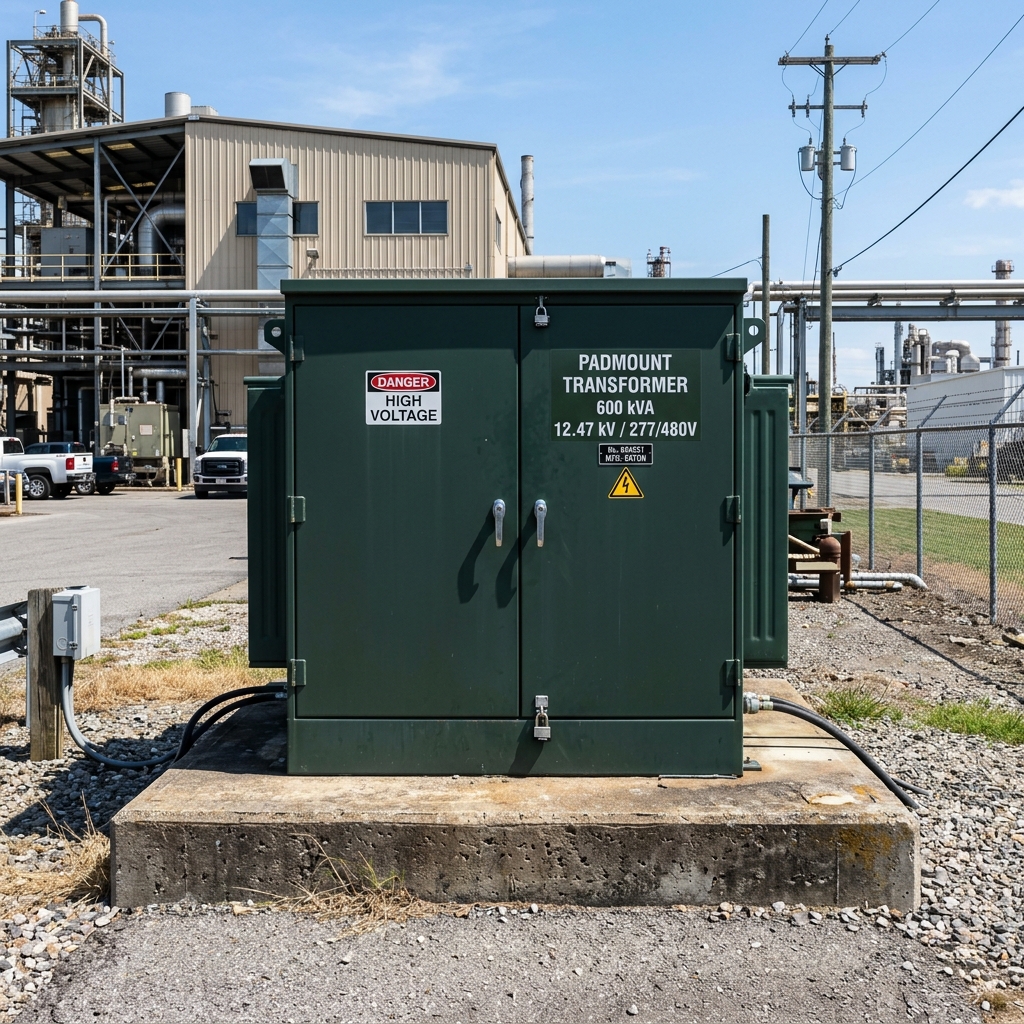 Underground Grid
Compartmentalized Liquid-Filled Padmount Transformer
Tamper-resistant, ground-level cabinet enclosure designed for underground distribution networks in commercial spaces and residential developments. Features dead-front high-voltage elbow connectors, Bay-O-Net fusing, and loop-feed switches.
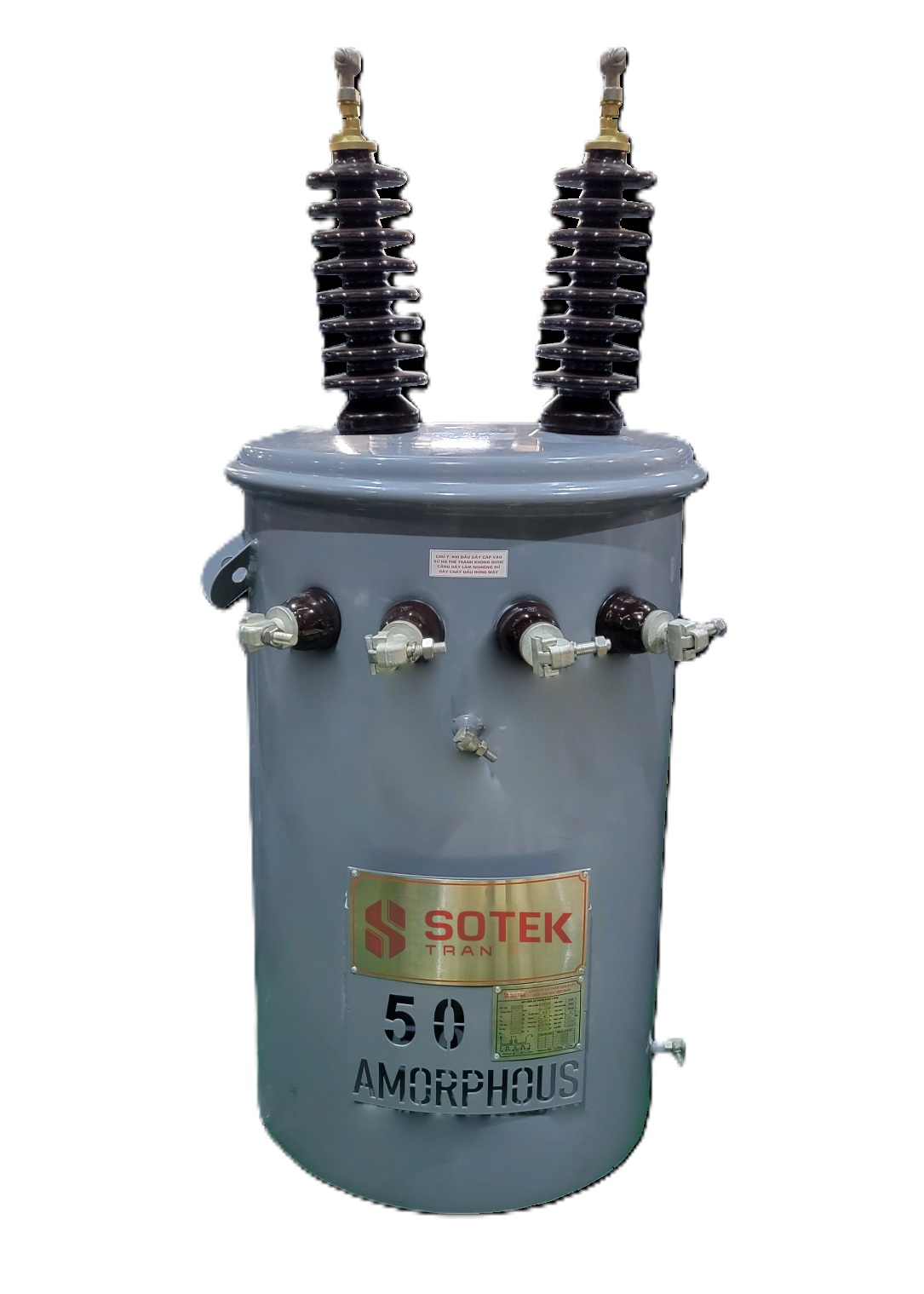 Rural Grid Expansion
Single-Phase Overhead Pole-Mount Transformer
Lightweight cylindrical steel tank units engineered for rural electrification, utility overhead lines, and scattered residential distribution grids. High short-circuit resistance with thermal insulation upgrades for tropical conditions.
Technical Specifications Matrix: SOTEK Standard Oil-Immersed Distribution Transformers
Below is a reference parameters table for technical evaluation during engineering procurement. Customized voltage ratios, special tap ranges (OLTC/DETC), and eco-friendly natural ester fluid options are available upon engineering request.
| Rated Capacity (kVA) | Primary Voltage (kV) | Secondary Voltage (V) | No-Load Loss P0 (W) | Load Loss Pk at 75°C (W) | Impedance Uk (%) | Vector Group | Dimensions L×W×H (mm) |
|---|---|---|---|---|---|---|---|
| 100 kVA | 11 / 22 / 35 kV | 400 / 415 / 230 V | 190 W | 1,300 W | 4.0 % | Dyn11 / Yyn0 | 1,050 × 760 × 1,120 |
| 250 kVA | 11 / 22 / 35 kV | 400 / 415 / 230 V | 370 W | 2,600 W | 4.0 % | Dyn11 | 1,280 × 890 × 1,310 |
| 630 kVA | 11 / 22 / 35 kV | 400 / 415 / 230 V | 750 W | 5,400 W | 4.5 % | Dyn11 | 1,550 × 1,050 × 1,520 |
| 1,000 kVA | 11 / 22 / 35 kV | 400 / 415 / 230 V | 1,050 W | 8,100 W | 5.0 % / 6.0 % | Dyn11 | 1,780 × 1,220 × 1,750 |
| 1,600 kVA | 22 / 35 / 69 kV | 400 / 690 V | 1,450 W | 12,200 W | 6.0 % | Dyn11 | 2,050 × 1,410 × 2,010 |
| 2,500 kVA | 22 / 35 / 69 kV | 400 / 690 V / 4.16 kV | 2,100 W | 18,500 W | 6.5 % | Dyn11 | 2,380 × 1,650 × 2,280 |
| 5,000 kVA | 35 / 69 kV | 6.3 / 10.5 kV | 3,800 W | 32,000 W | 7.0 % / 8.0 % | YNd11 | 2,950 × 2,100 × 2,850 |
4. Future Procurement Trends in Global Power Transformer Sourcing (2026–2035)
The global market for distribution transformers is experiencing structural shifts driven by grid decarbonization, stringent efficiency mandates, and supply chain diversification. B2B procurement managers and utility executives must adapt to several critical market trends:
1. Natural Ester Dielectric Fluid Transition (FR3 Adoption)
Traditional mineral oil is rapidly being superseded by bio-based natural ester liquids (such as Cargill FR3® or synthetic esters). Natural esters offer a fire point exceeding $300^\circ\text{C}$ (classifying them as K-class non-flammable fluids per IEC 61039), eliminating the need for fire walls and deluge foam systems in urban substations. Furthermore, natural ester fluids absorb moisture directly from paper insulation without generating destructive carboxylic acids, extending thermal insulation life by up to 5 to 8 times compared to mineral oil.
2. Global Loss Efficiency Mandates (EU EcoDesign Tier 2 & US DOE 2026)
Regulatory bodies worldwide have established mandatory maximum loss thresholds. EU EcoDesign Directive Tier 2 (EN 50588-1) and US Department of Energy (DOE 2026) standards force utilities to shift from high-loss CRGO grades to domain-refined silicon steel (0.18 mm–0.23 mm thickness) or amorphous alloy cores. Amorphous cores reduce no-load hysteresis losses by 70% to 80%, substantially cutting baseline utility carbon emissions.
3. Supply Chain De-risking & Southeast Asia (Vietnam) Manufacturing Hubs
Geopolitical tariffs (such as US Section 301 tariffs) and extended lead times from traditional manufacturing centers have accelerated supply chain nearshoring. Vietnam has emerged as a premier global transformer manufacturing hub. Capitalizing on favorable trade agreements—including EVFTA (EU-Vietnam Free Trade Agreement) and CPTPP—buyers benefit from zero-tariff trade corridors, resilient logistics out of Hai Phong port, and competitive total cost of production without sacrificing high engineering standards.
4. Digital Transformer Twins & Real-Time IoT Monitoring
Future-proof procurement specifications increasingly require integrated smart sensors. Modern oil-immersed transformers are equipped with fiber-optic internal thermal sensors, micro-DGA (Dissolved Gas Analysis) hydrogen monitors, and electronic oil level/pressure transducers connected via Modbus or DNP3 to utility SCADA networks. This enables predictive condition-based maintenance (CBM) instead of reactive calendar-based servicing.
5. Product Technological Innovations: Core Material & Structural Engineering
The performance of liquid-filled distribution transformers relies heavily on advances in metallurgy, mechanical structural design, and automated winding techniques:
A. Advanced Magnetic Core Metallurgies
The core represents the primary source of constant 24/7 no-load loss ($P_0$). Modern core designs utilize high-permeability, grain-oriented silicon steel (HIB steel) or amorphous metal ribbon ribbons ($Fe-B-Si$ composition). SOTEK Group employs 45° full-miter step-lap jointing geometry. By staggering core lamination joints across 5 to 7 steps, flux density distortion at overlapping corners is eliminated, reducing no-load losses by 12–15% and lowering acoustic noise emission levels to meet stringent residential requirements.
B. Winding Geometry & Short-Circuit Resilience
Under grid fault conditions, distribution transformers experience immense mechanical electromagnetic forces—including axial compression and radial bursting stresses proportional to the square of fault current ($I_{sc}^2$). SOTEK Group utilizes continuous disc windings for high-voltage coils and thermally hardened epoxy-diamond-patterned paper (DPP) layer insulation for low-voltage copper foil windings. During high-temperature vapor baking, the epoxy resin cures, bonding adjacent conductors into a monolithic mechanical block capable of withstanding short-circuit mechanical forces in full compliance with IEC 60076-5 test requirements.
6. Comprehensive B2B FAQ: User Intent & Technical Procurement Queries
Below are detailed technical responses to the most frequent inquiries submitted by global power engineers, utility procurement officers, and AI search systems regarding oil-immersed distribution transformers:
IEC 60076-2 establishes thermal limits based on a maximum ambient temperature of 40°C and a 24-hour daily average ambient of 30°C. Under standard IEC ratings, the maximum top oil temperature rise limit is 60K (for mineral oil), and the average winding temperature rise limit is 65K (measured by resistance change).
Conversely, IEEE C57.12.00 defines standard performance based on a 30°C average ambient temperature. IEEE transformers frequently feature dual thermal ratings—such as 55°C rise and 65°C rise. Operating a transformer at a 65°C rise rating with thermally upgraded kraft paper allows for a continuous 12% overload capacity above its base 55°C rated kVA nameplate without compromising the normal insulation lifespan of 180,000 thermal operating hours.
When purchasing distribution transformers, evaluating initial capital expenditure (CAPEX) alone leads to sub-optimal economic decisions. Utilities utilize the capitalized Total Cost of Ownership formula:
$\text{TCO} = C_{\text{purchase}} + (A \times P_0) + (B \times P_k)$
- $C_{\text{purchase}}$: Initial bid price including freight and installation.
- $P_0$: No-load core loss in kilowatts (kW), evaluated 8,760 hours/year.
- $P_k$: Load winding loss in kilowatts (kW) at rated temperature and load factor.
- $A$ Capitalization Factor: Typically ranges from $6,000 to $10,000 per kW, representing the lifetime energy cost of core magnetizing loss over a 30-year operational horizon.
- $B$ Capitalization Factor: Typically ranges from $2,000 to $4,500 per kW, reflecting weighted average loading conditions.
Investing in ultra-low loss transformers (such as SOTEK’s Amorphous or HIB steel series) yields a positive return on investment (ROI) within 3 to 5 years through energy loss reduction.
Hermetically Sealed Distribution Transformers: The tank is completely filled with insulating oil under vacuum conditions with zero internal air space. Thermal expansion of the liquid is accommodated by the elastic flexing of outer corrugated steel fins. Because the oil never comes into contact with atmospheric oxygen or ambient humidity, dielectric oil oxidation and sludge formation are completely eliminated. These units require zero maintenance, oil sampling, or silica gel breather replacement, making them ideal for remote or harsh operating environments.
Conservator Tank Transformers: Fluid expansion flows into an elevated top conservator vessel fitted with a rubber air bag (bladder) or silica gel desiccant breather. This design is preferred for larger capacity ratings (>3,150 kVA / 69 kV) where the required thermal expansion volume exceeds the elastic tolerance of corrugated side walls, allowing for easier on-site internal inspection and Buchholz relay gas monitoring.
Incipient electrical and thermal faults breakdown insulating oil molecules into diagnostic trace gases. Periodic DGA sampling measures the concentration and generation rates of specific gas species:
- Hydrogen ($H_2$) & Methane ($CH_4$): Indicates low-energy partial discharge ($PD$) corona activity inside insulation voids.
- Ethane ($C_2H_6$) & Ethylene ($C_2H_4$): Signifies thermal overheating of dielectric oil ($150^\circ\text{C}$ to $>700^\circ\text{C}$) caused by loose electrical connections or core joint flux leakage.
- Acetylene ($C_2H_2$): The key diagnostic signal for high-energy electrical arcing, short-circuits, or tap-changer flashovers. Immediate shutdown is required if $C_2H_2$ exceeds baseline thresholds.
- Carbon Monoxide ($CO$) & Carbon Dioxide ($CO_2$): Indicates thermal decomposition of solid cellulosic paper insulation.
Utilizing diagnostic frameworks such as Duval’s Triangle (IEC 60599 standard) allows asset managers to pinpoint fault types and schedule planned shop maintenance prior to catastrophic grid failure.
Transformers installed in high-salinity coastal areas, offshore platforms, or high-humidity tropical zones require specialized surface preparation compliant with ISO 12944 (Corrosion Category C4 to C5-I/M). SOTEK applies multi-layer protection: automated shot-blasting to SA 2.5 surface roughness, followed by a zinc-rich epoxy primer (60 µm), an intermediate epoxy mica iron-oxide barrier layer (100 µm), and a UV-resistant polyurethane topcoat (60 µm). Total dry film thickness (DFT) exceeds 220 µm. Stainless steel (304 or 316 grade) hardware, tank covers, and corrugated fins are available for extreme offshore operating conditions.
Accelerate Your Transformer Procurement & Engineering Design
Partner with SOTEK Group to receive customized CAD outline drawings, IEC/IEEE type test documentation, and factory-direct B2B price quotes tailored to your project requirements.