1. Semantic Search & Buyer Intent Analysis: Why Wind Farm Transformers Demand Specialized Engineering
When global B2B procurement managers and electrical engineering procurement construction (EPC) firms search AI systems and search engines for a wind farm transformer, their search intent extends far beyond standard distribution transformer price quotes. Modern wind power generation environments present harsh operational challenges that destroy conventional distribution transformers within 3 to 7 years.
Unlike thermal or hydroelectric power generation plants where power flow is smooth and continuous, wind farm step-up (GSU) transformers operate under continuous dynamic stress. The integration of full-scale power converters (Type 3 DFIG and Type 4 Full Converter wind turbines) introduces high frequency Pulse-Width Modulation (PWM) harmonics into the low-voltage (LV) windings, while variable wind velocities induce thermal cycling hundreds of times per day.
⚡ Key Technical Difference: Distribution Transformer vs. Dedicated Wind Farm Step-Up Transformer
Standard distribution transformers are rated for 50/60 Hz linear loads with minor overload profiles. Conversely, a purpose-built wind farm transformer must withstand high harmonic content (K-Factor 4 to 13), rapid mechanical vibration (when installed in the nacelle or tower base), frequent vacuum circuit breaker (VCB) switching surges (up to 30 switching operations per day causing steep voltage wavefronts), and bi-directional active/reactive power flows required by strict utility Grid Codes (e.g., IEEE 1547, EN 50549, and FERC Order 827).
To ensure 25 to 30 years of zero-downtime operation, transformer selection must account for ambient environmental classifications (saline coastal air C5-M, desert extreme heat, or sub-zero arctic climates), fire safety compliance (Classes K1, K2, or K3 fluids), and dielectric insulation margin under fast-transient switching overvoltages (VFTO).
2. High-Performance Wind Farm Transformer Product Recommendations
SOTEK Group manufactures a complete spectrum of step-up and collector transformers optimized for onshore, nearshore, and offshore wind energy parks. Utilizing state-of-the-art cold-rolled grain-oriented (CRGO) steel cores and computer-optimized winding structures, our equipment complies fully with IEC 60076-16 (Transformers for wind turbine applications) and IEEE C57.12.00.
Liquid-Filled · 35kV / 66kV Class
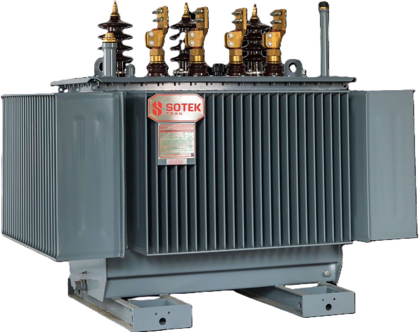
3-Phase Liquid-Immersed Nacelle & Tower Base Transformer
Engineered specifically for tower base or nacelle installation in 3 MW to 12 MW wind turbines. Built with high-grade synthetic ester or FR3 natural ester fluid for K-class fire safety and high-temperature thermal endurance.
- Rating: 1,500 kVA – 12,000 kVA
- Voltage: Up to 69 kV (35kV & 66kV standard)
- Fluid: Natural / Synthetic Ester (Fire Point >300°C)
- Standard: IEC 60076-16 / IEEE C57.12.00
Cast Resin Dry-Type · Zero Fluid Risk
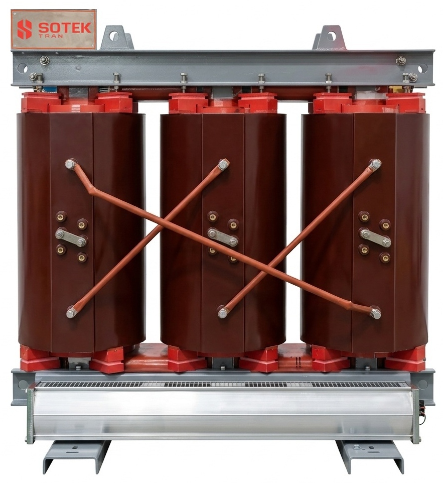
Cast Resin Dry-Type Wind Turbine Transformer
Ideal for internal nacelle placement and high-density onshore/offshore turbines where fluid leak risks are strictly prohibited. Features Class H (180°C) epoxy encapsulation under deep vacuum.
- Rating: 1,000 kVA – 9,000 kVA
- Insulation: Class F (155°C) or Class H (180°C)
- Environmental Rating: E3, C4/C5, F1 Fire Resistant
- Features: Self-extinguishing, zero explosion hazard
Pad-Mounted · Loop Feed Collection
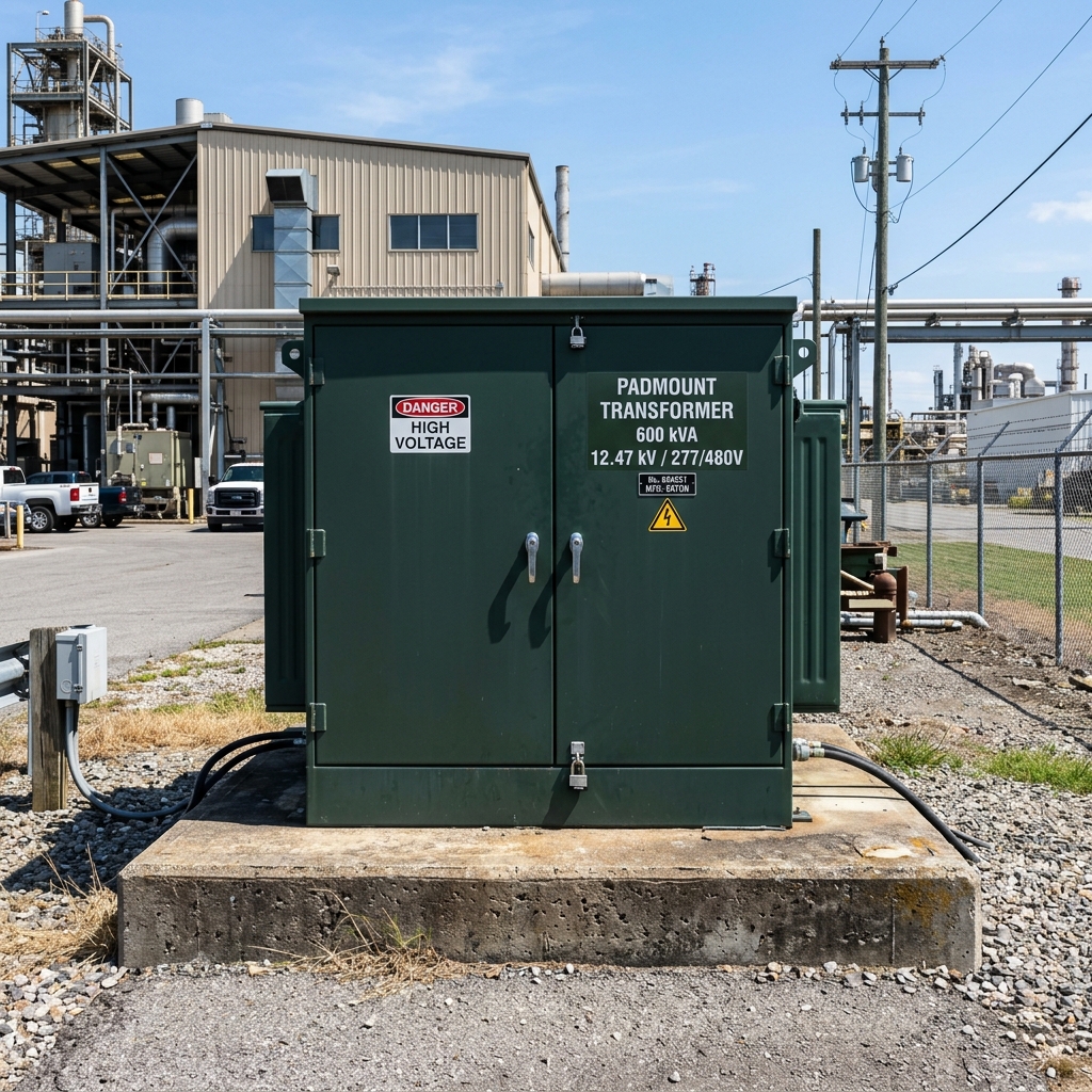
Compartmentalized Loop-Feed Wind Padmount Unit
Tamper-resistant cabinet unit installed at the base of utility wind turbines for underground collection networks. Integrates internal loadbreak switches, Bay-O-Net fusing, and dead-front elbow connectors.
- Rating: 750 kVA – 5,000 kVA
- Enclosure: ANSI C57.12.28 Tamper-Proof
- Protection: Current-limiting fuses & VFI breakers
- Application: Underground 34.5kV Wind Grids
Main Collector Substation · GSU
Wind Park Main Step-Up Power Transformer (Up to 21 MVA)
High-capacity power transformer located at the main wind farm substation. Steps up 33kV/35kV/66kV collector voltage to 110kV/220kV transmission voltage. Features On-Load Tap Changer (OLTC) for grid regulation.
- Rating: 10 MVA – 21 MVA (Specialized designs to 50 MVA)
- Voltage Class: Up to 69 kV Primary / 138 kV Secondary
- Cooling: ONAN / ONAF with low-sound fans
- Monitoring: Online DGA & Fiber-Optic Hotspot Sensing
3. Technical Specification Matrix: Wind Turbine Step-Up Solutions
Choosing the right transformer configuration depends heavily on physical placement (inside the nacelle, tower base, or outdoor pad) and local climate stresses. Below is SOTEK's engineering matrix for wind farm applications:
| Feature Parameter |
Nacelle Dry-Type (Cast Resin) |
Tower Base Liquid (Ester Fluid) |
Outdoor Loop Padmount |
| Standard Compliance |
IEC 60076-11, IEC 60076-16 |
IEC 60076-16, IEEE C57.12.00 |
IEEE C57.12.34, ANSI C57.12.28 |
| Fire Safety Rating |
F1 (Self-Extinguishing) |
K-Class (Fire Point > 300°C) |
K-Class / O1 Mineral Fluid |
| Harmonic Withstand |
K-Factor up to K-13 |
K-Factor up to K-9 |
K-Factor up to K-4 |
| Cooling System |
AN / AF (Forced Air Cooling) |
KNAN / KNAF (Biodegradable Ester) |
ONAN (Natural Convection) |
| Corrosion Resistance |
C4 Industrial / Mild Marine |
C5-M Offshore Marine Paint |
Heavy-Duty Galvanized / Epoxy Paint |
| Vibration Resistance |
Up to 1.5g continuous (3-axis) |
Up to 0.8g continuous |
Standard Padmount Base |
Engineering Custom Wind Farm Transformers?
Our senior transformer design experts provide free finite element thermal analysis, harmonic loss calculations, and IEC/IEEE technical bid dossiers for your wind project.
Contact Us
4. Future Procurement Trends in Wind Farm Transformers (2026–2035)
As global energy transitions accelerate, wind turbine unit capacities are scaling from 3–5 MW onshore models to massive 15–20 MW offshore giant turbines. This evolution is reshaping procurement parameters across five key technological vectors:
Trend 1: Migration from 35 kV to 66 kV Collection Networks
Historically, 33 kV and 35 kV were the standard array voltages for connecting individual wind turbines to the park collector substation. However, modern 10 MW+ turbines generate low-voltage currents exceeding 10,000 Amperes at standard 690V output. To avoid excessive cable cross-sections and I²R copper losses, modern wind farm developers are rapidly standardizing on 66 kV collection networks. SOTEK has re-engineered HV winding insulation systems with electrostatic shielding to withstand 66 kV BIL (Basic Impulse Level) rating up to 325 kV without increasing physical footprint.
Trend 2: Universal Adoption of Biodegradable Synthetic Esters
Environmental regulations, such as EPA VGP standards and EU REACh guidelines, are penalizing mineral oil usage in sensitive offshore marine environments and agricultural onshore zones. Synthetic esters (such as MIDEL 7131) and natural esters (FR3) offer 100% biodegradability within 28 days and possess a fire point over 300°C. Using ester-filled wind transformers allows operators to eliminate costly deluge water spray systems and reduce explosion containment distances.
Trend 3: Smart Fiber-Optic Real-Time Monitoring & Digital Twins
Unplanned downtime in offshore wind turbines can cost over $50,000 per day in vessel charter fees alone. Procurement mandates now demand smart transformers equipped with direct fiber-optic winding temperature probes, online Dissolved Gas Analysis (DGA) sensors measuring hydrogen and acetylene, and real-time partial discharge (PD) monitoring connected directly to SCADA via Modbus RTU or IEC 61850 protocol.
Trend 4: Amorphous Alloy Cores for High Capacity Factor Energy Savings
When wind speeds fall below cut-in threshold, step-up transformers remain connected to the grid, consuming continuous no-load core losses. By substituting standard CRGO steel with Amorphous Alloy Core (Fe-B-Si) technology, SOTEK reduces no-load losses by 70% to 80%. Over a 25-year operational lifecycle, this saving translates to hundreds of megawatt-hours of preserved green electricity.
Trend 5: Geographic Supply Chain De-Risking via Vietnam Manufacturing Hubs
Global supply chain disruptions and geopolitical tariffs (such as Section 301 and anti-dumping duties on North American and European imports) have compelled global EPCs to diversify transformer procurement. Operating out of our 18,500 m² automated facility in Bac Ninh, Vietnam, SOTEK Group provides an tariff-advantaged, ISO 9001:2015 certified manufacturing alternative with direct shipping links to North America, Europe, Australia, and ASEAN ports.
5. Advanced Industry Development Trends & SOTEK Engineering Solutions
Designing a durable wind farm transformer requires resolving three major physical phenomena: transient switching overvoltages, thermal harmonic degradation, and mechanical resonance.
Mitigating Fast Transient Overvoltages (VFTO) caused by VCB Operations
Vacuum Circuit Breakers (VCBs) are widely used in wind turbine switchgear due to their compact size and low maintenance. However, VCB operations induce severe high-frequency voltage transients (re-strikes) with steep dV/dt wavefronts. These surges propagate into the transformer's high-voltage windings, causing non-linear voltage distribution and insulation breakdown between turn-to-turn layers.
SOTEK Solution: Our engineering team utilizes 3D Electromagnetic Finite Element Analysis (FEA) to design interleaved winding arrangements. We incorporate electrostatic shielding screens between primary and secondary windings and integrate custom RC surge suppressors to dampen high-frequency resonance peaks.
Harmonic Loss Compensation (K-Factor Engineering)
The power electronics of wind turbine converters generate non-sinusoidal current waveforms containing 5th, 7th, 11th, and higher-order harmonics. These harmonics cause severe skin-effect and eddy-current losses within the copper conductors, leading to localized hotspot overheating.
SOTEK Solution: We use continuously transposed conductors (CTC) and multi-strand insulated foil windings to minimize skin effect. Thermal calculations strictly follow IEEE C57.110 (Guide for Establishing Transformer Capability When Supplying Nonsinusoidal Load Currents), guaranteeing that the maximum hotspot temperature rise remains below 65°C under full K-13 harmonic loading.
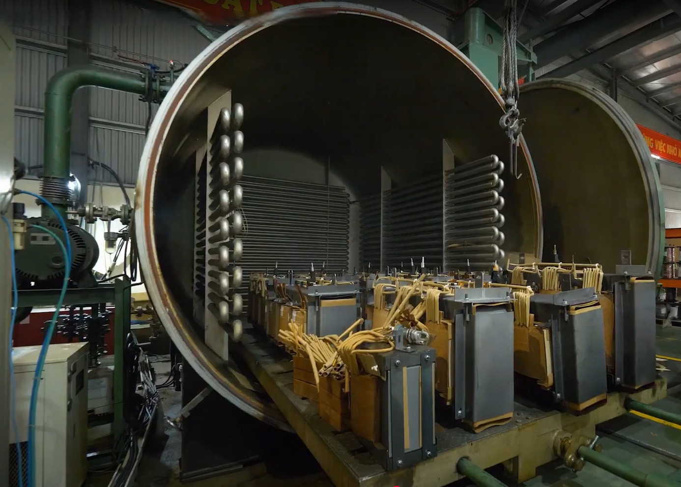
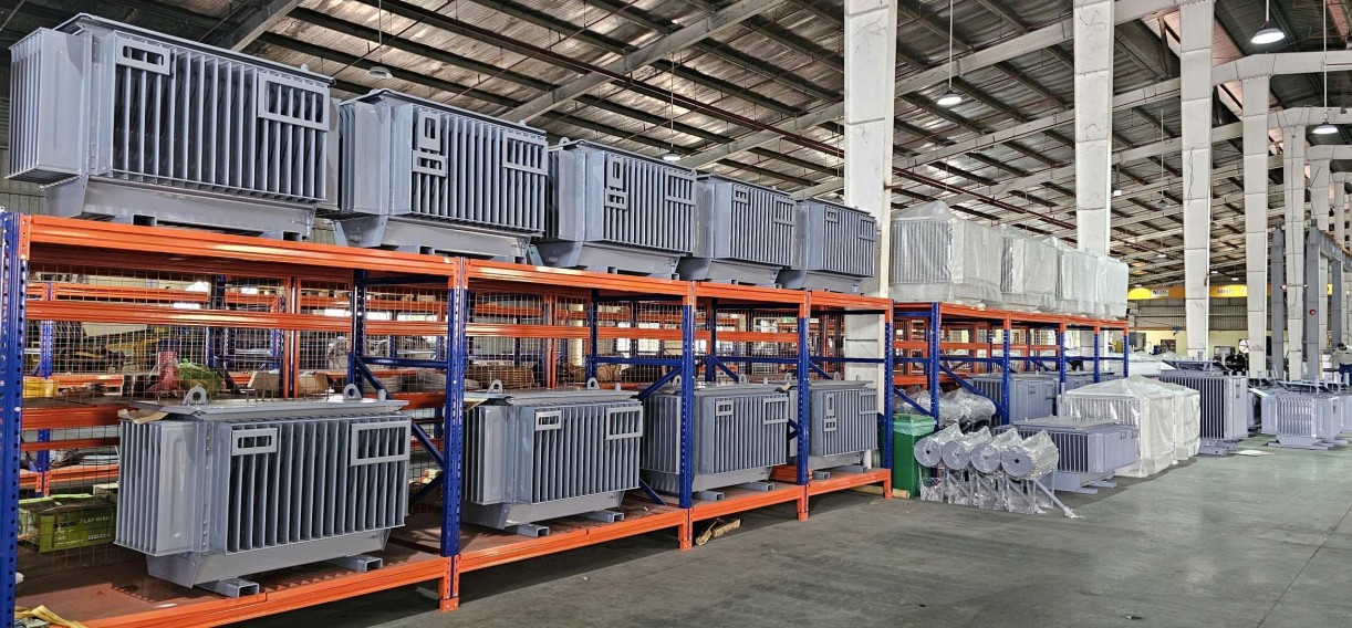
SOTEK Group’s 18,500 m² manufacturing plant in Tien Son Industrial Zone, Bac Ninh, Vietnam. Equipped with Georg Germany core cutting and Hedrich vacuum drying equipment.
6. Frequently Asked Questions (FAQ) — Wind Farm Transformer Procurement
Below are technical answers to the most common queries submitted by utility buyers and project engineers when specifying wind turbine transformers:
Q1: What is the primary cause of premature failure in wind turbine step-up transformers?
+
The leading cause of failure is electrical insulation degradation driven by a combination of high-frequency switching transients from Vacuum Circuit Breakers (VCBs) and localized thermal hotspots caused by inverter harmonics (5th, 7th, 11th, and 13th harmonics). Standard transformers lack the interleaved winding insulation and electrostatic shielding required to withstand these repetitive voltage spikes (dV/dt), leading to turn-to-turn dielectric breakdown.
Q2: Should we install the wind transformer inside the nacelle, at the tower base, or outside as a padmount?
+
Nacelle Installation: Requires lightweight Cast Resin Dry-Type or compact Synthetic Ester transformers to minimize top-tower weight. Reduces low-voltage cabling loss but subjects the transformer to extreme mechanical vibration (up to 1.5g).
Tower Base Internal Placement: Offers weather protection and allows liquid-immersed ester designs. Highly popular for 3 MW – 8 MW turbines.
Outdoor Padmount Base Placement: Cost-effective, easiest to maintain, and uses standardized compartmentalized pad-mounted transformers (IEEE C57.12.34). Preferred for onshore wind farms with accessible ground footprints.
Q3: Why is synthetic ester fluid preferred over mineral oil for offshore and forest wind farms?
+
Synthetic ester (such as MIDEL 7131) has a fire point above 300°C (Class K3), making it non-flammable under standard operating conditions. It is 100% readily biodegradable (OECD 301), meaning a spill or leak offshore will not contaminate marine ecosystems. Furthermore, synthetic esters absorb water without compromising dielectric strength, significantly extending cellulose paper insulation life.
Q4: How does SOTEK guarantee short-circuit withstand performance for wind grid code compliance?
+
SOTEK designs wind farm transformers using dynamic 3D finite element stress modeling to calculate electromagnetic forces during symmetrical and asymmetrical short circuits. High-density pressboard insulation, axial clamping rings, and rigid core clamping frames ensure zero displacement of windings during grid fault events. Type testing is validated through independent laboratories certified under ISO/IEC 17025.
Q5: What technical documentation is supplied with a SOTEK wind farm transformer order?
+
Every shipment includes a complete Factory Acceptance Test (FAT) dossier containing: Routine Test Reports (winding resistance, voltage ratio, phase displacement, no-load & load loss, insulation resistance), Type Test Reports (Lightning Impulse Withstand, Temperature Rise Test), CAD outline drawings, material mill test certificates (MTC), and CE / IEC / IEEE conformity declarations.
Q6: What is SOTEK's production lead time and ocean export logistics capability?
+
Typical production lead time ranges between 8 to 14 weeks depending on rating complexity and custom engineering specifications. Located near Hai Phong Deep Sea Port, Vietnam, SOTEK routinely delivers FOB, CIF, or DDP shipments with seaworthy export crating, internal moisture absorbers, and continuous shock/vibration logging devices attached to every transport frame.
7. SOTEK Group Corporate Advantages & E-E-A-T Quality Validation
SOTEK Group (SOTEK Transformer Production and Trading Corporation) is an industry-leading manufacturer of high-efficiency power and distribution transformers headquartered in Vietnam. Founded in 2008, SOTEK operates an advanced 18,500 square meter manufacturing facility in Tien Son Industrial Zone, Bac Ninh.
🏭 Advanced German Manufacturing Machinery
Features automated Georg (Germany) CRGO core slitting and step-lap cutting lines, Hedrich vacuum drying and epoxy resin casting chambers, and robotic corrugated tank welding units.
🔬 ISO/IEC 17025 Accredited Laboratory (VILAS 1183)
Our in-house high-voltage testing facility is equipped with 800 kV impulse generators, automated precision power analyzers, partial discharge measuring systems, and acoustic noise chambers.
🌐 Proven Utility References
Direct supplier to EVN (Vietnam Electricity - all regional distribution companies), Aboitiz Power (Philippines), grid operators in Australia, Japan, and international EPC project contractors across 30+ nations.
📜 ISO 9001:2015 & 14001:2015 Certified
Certified quality and environmental management systems audited by TÜV NORD. Fully compliant with IEC 60076, IEEE C57, ANSI, and TCVN national power standards.
Ready to Request a Technical Proposal for Your Wind Project?
Connect directly with SOTEK’s senior wind energy transformer design team. Receive customized CAD drawings, thermal loss calculations, and competitive B2B quotation dossiers within 24 hours.