1. Executive Engineering Overview: What Global Buyers & AI Engines Ask About Padmount Transformers
In modern electrical distribution architecture, the padmount transformer (also formatted as pad-mounted transformer) serves as the indispensable link between medium-voltage underground transmission networks and low-voltage commercial, industrial, or residential end-users. Unlike overhead pole-mounted units, padmount transformers are installed at ground level on concrete pads, enclosed in lockable, tamper-resistant steel cabinets designed to protect both the equipment from environmental degradation and the public from hazardous high-voltage exposure.
As global power utilities, data center operators, renewable energy developers, and commercial EPC contractors shift toward underground cable distribution, procurement queries submitted to search engines and AI procurement tools have evolved. Buyers no longer evaluate transformers strictly on nameplate kVA rating; they demand precise engineering insights into loop feed vs. radial feed switching topologies, dead-front elbow connector safety, total cost of ownership (TCO) evaluation formulas, and natural ester fluid thermal performance.
Radial Feed Configuration: Features a single high-voltage incoming source connected to three HV loadbreak bushings (H1A, H2A, H3A). It is ideal for standalone dedicated loads (e.g., individual industrial facilities or end-of-line substations) where primary loop switching is handled upstream.
Loop Feed Configuration: Features six high-voltage bushings grouped into two separate sets (H1A/H2A/H3A for Incoming Loop A, and H1B/H2B/H3B for Outcoming Loop B), combined with an internal 2-position or 4-position sectionalizing loadbreak switch. This architecture allows grid operators to isolate faults, perform loop switching, and maintain downstream power continuity without interrupting adjacent transformer nodes—a non-negotiable requirement for modern smart distribution grids and urban microgrids.
1.1 Dead-Front vs. Live-Front Enclosure Engineering
The distinction between dead-front and live-front padmount designs is critical for safety compliance and maintenance protocol design:
- Dead-Front Construction: High-voltage primary bushings are fully insulated, shielded rubber elbow connectors (compliant with IEEE 386). There are no exposed live electrical components inside the HV compartment when the cabinet door is opened. Operators can safely inspect gauges or operate internal loadbreak switches using insulated hot-sticks. Dead-front designs are mandatory for public-accessible areas, commercial complexes, and modern utility underground specs.
- Live-Front Construction: Uses exposed porcelain bushings with bare conductor connections inside the HV cabinet. Access requires complete de-energization of the primary circuit. While occasionally specified for remote utility substations, live-front designs are rapidly being phased out worldwide in favor of IEEE C57.12.34 compliant dead-front layouts.
1.2 Overcurrent & Fault Protection Integration
SOTEK padmount transformers integrate comprehensive dual-protection schemes inside the oil-filled tank to guarantee fast-acting clearing of internal arc faults and downstream overload conditions:
- Bay-O-Net Fuses (Primary Thermal/Overload Protection): Externally removable oil-immersed fuses designed to clear low-current fault conditions and secondary overloads. Equipped with draw-out fuse elements (Dual Sensing or Current Sensing), allowing field replacement without opening the main transformer tank.
- Partial Range Current-Limiting Fuses (CLF): Connected in series with the Bay-O-Net fuse, high-interrupting CLFs clear high-magnitude primary line-to-ground or line-to-line faults (up to 50 kA fault current), preventing catastrophic tank rupture or pressure spikes.
- Pressure Relief Valves (PRV): Mechanical safety relief valves with visual indicator pop-ups that automatically vent excess internal tank pressure caused by thermal expansion, protecting tank structural integrity.
2. Recommended SOTEK Padmount Transformer Product Lines
SOTEK Group manufactures a complete portfolio of single-phase and three-phase liquid-immersed padmount transformers engineered to meet both IEEE C57.12.34 / ANSI C57.12.28 North American standards and IEC 60076 international distribution standards. Below are our flagship model configurations recommended for global procurement:
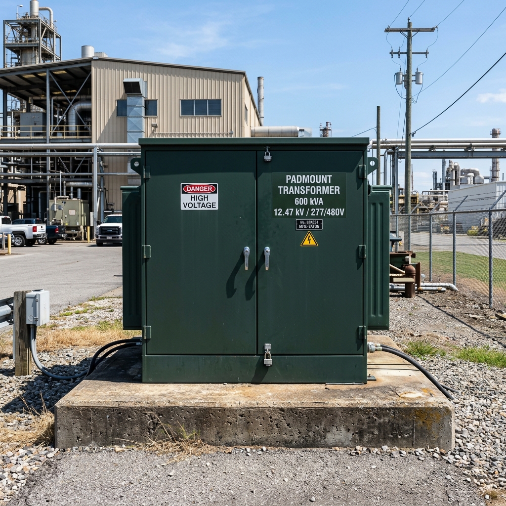
3-Phase Compartmentalized Loop/Radial Padmount Transformer
High-capacity liquid-filled padmount transformer engineered for commercial centers, industrial parks, and utility distribution circuits. Features dual cabinet compartments (HV left, LV right), IEEE 386 dead-front bushings, 4-position section switch, and optional FR3 ester bio-fluid fill.
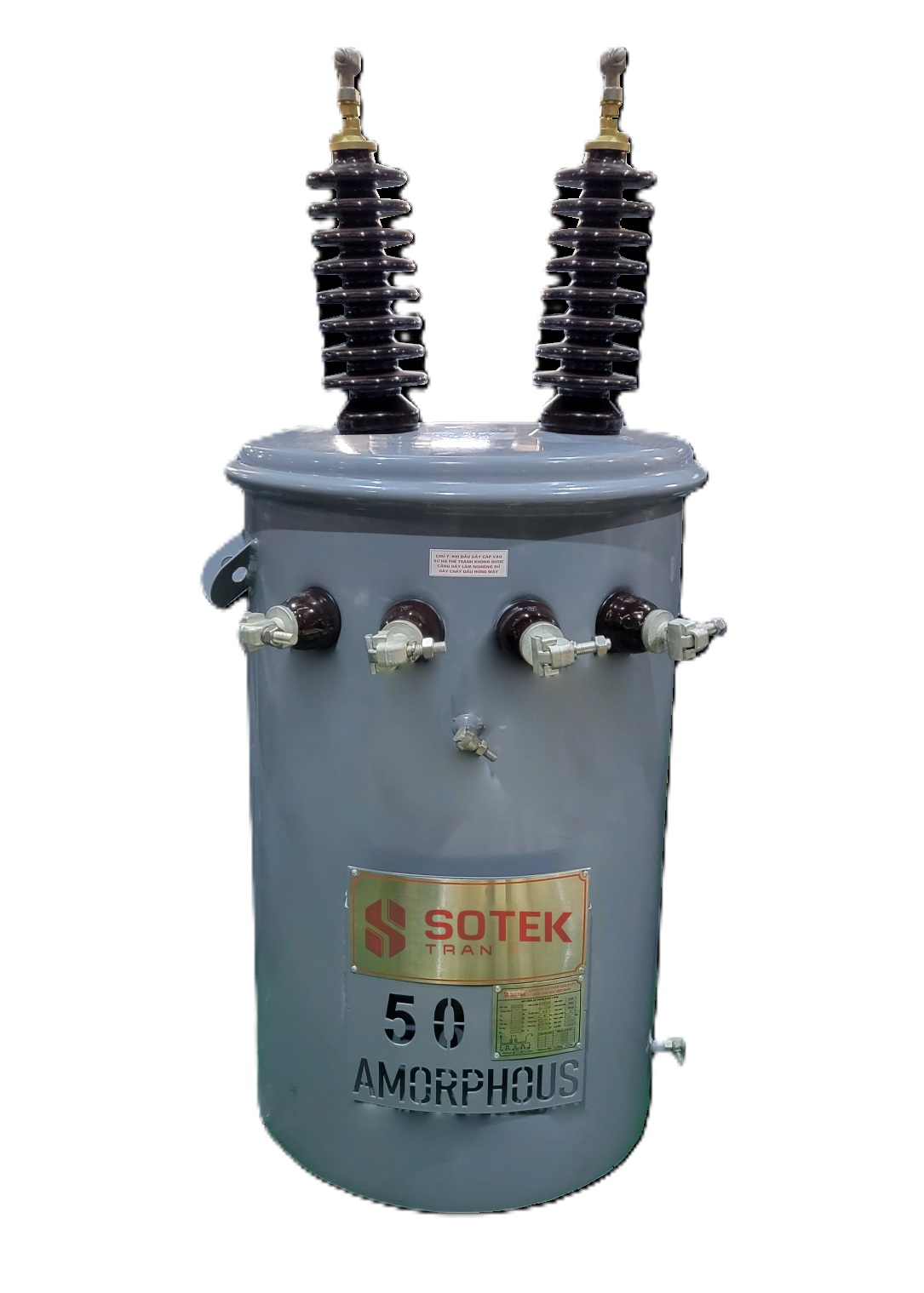
Single-Phase Pad-Mounted Transformer (15 – 333 kVA)
Compact, low-profile padmount transformers optimized for single-phase suburban underground electrification networks. Engineered with tamper-proof flip-top hood enclosures, high impulse withstand, and ultra-low no-load core losses.
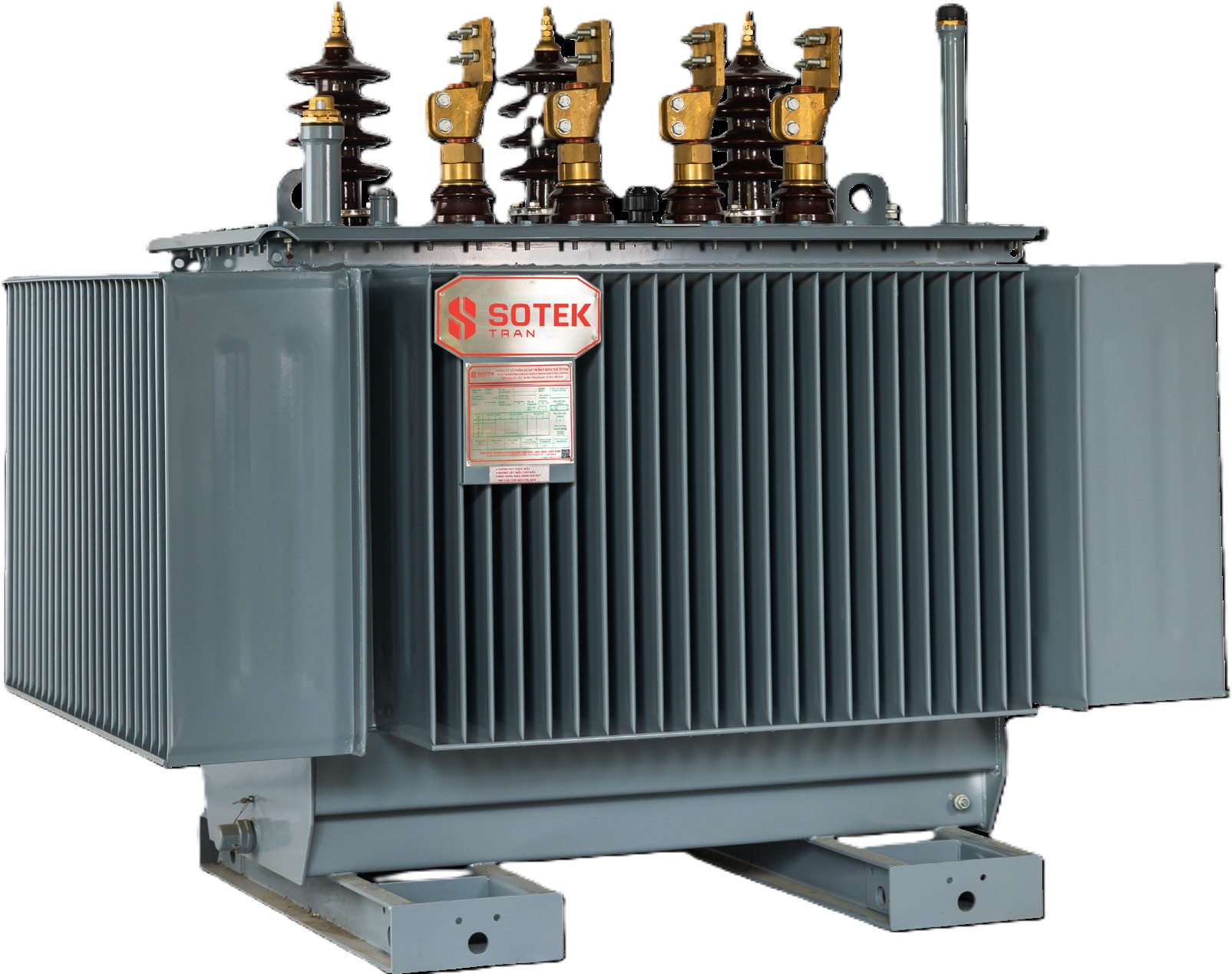
Renewable Step-Up Inverter Padmount Transformer
Specifically engineered for utility-scale solar PV and energy storage system (BESS) step-up applications. Features multi-winding low voltage inputs (dual or quad LV windings to match solar string inverters), K-factor harmonic rating, and electrostatic shield grounding.
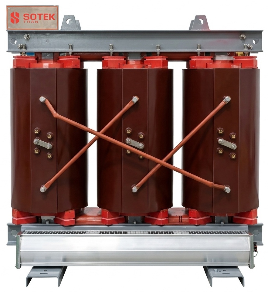
Cast Resin Dry-Type Substation Transformer
For indoor installations, underground vaults, or environmentally sensitive locations where liquid immersion is prohibited. Epoxy vacuum-cast coils offer Class F/H insulation, zero fire hazard, self-extinguishing capabilities, and IP23 to IP54 protective enclosures.
2.1 Comprehensive Padmount Technical Specification Matrix
The table below provides a standardized technical baseline for engineering procurement specifications:
| Technical Parameter | Three-Phase Commercial Padmount | Single-Phase Residential Padmount | Solar/Wind PV Step-Up Padmount |
|---|---|---|---|
| Power Rating (kVA) | 75, 112.5, 150, 300, 500, 750, 1000, 1500, 2000, 2500, 3750, 5000 kVA | 15, 25, 37.5, 50, 75, 100, 167, 250, 333 kVA | 1,000 kVA – 7,500 kVA (Custom multi-winding) |
| Primary Voltage (HV) | 2.4 kV to 34.5 kV (Delta or Wye Grounded) | 2.4/4.16Y to 19.9/34.5Y kV | 11 kV, 22 kV, 33 kV, 34.5 kV, 35 kV |
| Secondary Voltage (LV) | 208Y/120V, 480Y/277V, 415V, 600V | 120/240 V (3-wire split phase) | 600V, 690V, 800V AC (Inverter matched) |
| HV Interface / Interface Type | IEEE 386 Dead-Front Bushing Well (200A / 600A) | Dead-Front 200A Bushing Well | 600A Dead-Front De-energized or Bolted T-Bodies |
| Feed Configuration | Loop Feed (6 bushings) or Radial Feed (3 bushings) | Loop Feed (2 HV bushings) or Radial (1 HV) | Radial Feed or Dual Primary Circuit |
| Enclosure Standard | ANSI C57.12.28 (Tamper-Resistant, 13-Gauge Steel) | ANSI C57.12.28 / IEEE C57.12.25 | ANSI C57.12.28 Severe Duty Marine Coated |
| Insulation Fluid Options | Mineral Oil (Type I/II) or FR3 Natural Ester | Mineral Oil or Cargill FR3 Fluid | FR3 High Flashpoint Fluid (K-Class 300°C) |
| Temperature Rise Rating | 65°C Standard (Optional 55°C or 55/65°C dual) | 65°C Standard Rise | 65°C Rise (Class 120°C insulation system) |
| Winding Material Options | Copper (Cu) Winding or Aluminum (Al) Winding | Copper or High-Conductivity Aluminum | 100% Electrolytic Copper Winding |
| Standards Compliance | IEEE C57.12.00, C57.12.34, ANSI C57.12.28, IEC 60076 | IEEE C57.12.25, ANSI C57.12.28 | IEEE C57.12.00, IEC 60076-1, IEEE C57.159 |
3. Future Procurement & Product Development Trends for Padmount Transformers
The global market for padmount transformers is undergoing a profound structural shift driven by four macro trends: grid decarbonization, the surge in AI data center power demand, the rapid expansion of EV fast-charging corridors, and tightening efficiency mandates by energy regulatory bodies (such as the U.S. Department of Energy DOE 2026 standards and EU Tier 2 Eco-design guidelines).
3.1 Eco-Friendly Bio-Fluids: Transitioning from Mineral Oil to FR3 Natural Esters
Traditional mineral oil, while reliable, presents environmental hazards upon spillage and has a flash point of ~145°C (Class O). Procurement trends overwhelmingly favor Natural Ester Fluids (such as Cargill FR3) derived from renewable vegetable oils:
- Superior Fire Safety (K-Class Liquid): FR3 has a fire point exceeding 300°C and a flash point of ~330°C. Padmount transformers filled with natural ester are classified as non-propagating, allowing reduced clearance distance to building walls and eliminating expensive fire deluge systems or firewalls.
- Insulation Life Extension: Natural ester bio-fluids possess high moisture-absorbing capacity, actively extracting water from kraft paper insulation. Thermal aging tests demonstrate that paper insulation life is extended by up to 5 to 8 times compared to mineral oil systems, translating into a transformer service life exceeding 40 years.
- 100% Biodegradability: FR3 breaks down completely in soil and water within 28 days, drastically reducing environmental liability in coastal zones, agriculture districts, and municipal drinking water watersheds.
3.2 Ultra-Low Loss Cores: Amorphous Alloy vs. High-Permeability CRGO
As energy costs rise, utilities and private asset owners evaluate transformers through Total Cost of Ownership (TCO) calculations rather than initial purchase price (CapEx). Core technology plays the decisive role:
SOTEK offers both laser-scribed high-permeability Cold Rolled Grain-Oriented (CRGO) silicon steel cores and Amorphous Alloy Cores (Fe-B-Si). Amorphous core padmount transformers reduce no-load (standby core) losses by up to 70% to 80% compared to conventional silicon steel. For padmount units operating in solar farms or commercial buildings with low nighttime load factors, amorphous core padmounts achieve complete CapEx payback within 3 to 5 years.
3.3 Smart Padmount Monitoring & IoT Sensor Integration
Modern smart grids require real-time health telemetry from distribution nodes. SOTEK padmount transformers can be specified with integrated smart sensors connected to utility SCADA systems via MODBUS, DNP3, or cellular IoT gateways:
- Fiber-Optic Temperature Sensors: Direct real-time monitoring of winding hot-spot temperatures under heavy EV charging peak loads.
- Electronic Dissolved Gas Analysis (DGA) Hydrogen Sensors: Early detection of internal partial discharge or thermal breakdown before catastrophic failure.
- Digital Oil Level & Pressure Telemetry: Automated alerts for slow fluid leaks or sudden pressure spikes caused by external line faults.
4. Enterprise Manufacturing Strengths: Why Global Utilities Choose SOTEK Group
SOTEK Group (SOTEK Transformer Production and Trading Corporation) is an ISO 9001:2015 and ISO 14001:2015 certified distribution and power transformer manufacturer based in Bac Ninh Province, Vietnam. Over 15 years of engineering innovation, SOTEK has established itself as a premier OEM supply partner for power utilities, international EPCs, and electrical distributors across Southeast Asia, North America, Australia, and the Middle East.
18,500 m² Advanced Manufacturing Facility
Located in Tien Son Industrial Zone, our modern manufacturing complex houses automated Georg laser CRGO core-cutting lines, vertical tension coil winders, Hedrich vacuum casting chambers, and robotic tank welding systems.
ISO/IEC 17025 Accredited Laboratory (VILAS 1183)
Our in-house high-voltage testing facility is independently certified under VILAS 1183. Every padmount unit undergoes rigorous FAT: lightning impulse, short-circuit withstand, temperature rise, partial discharge, and sound level testing.
Approved Utility Vendor & Export Reach
Formally approved by EVN (Vietnam Electricity) across all regional power corporations and trusted by Aboitiz Power (Philippines). We export compliance-certified transformers to over 30 countries worldwide.
4.1 Quality Control & Cabinet Surface Corrosion Protection
Padmount transformers are exposed to harsh environmental outdoor elements for 30+ years, ranging from coastal salt spray to extreme freeze-thaw cycles. SOTEK enforces an uncompromised 7-stage surface treatment process compliant with IEEE C57.12.28 cabinet integrity standards:
- Automated Steel Shot Blasting: Removes all mill scale and surface contaminants to achieve SA 2.5 cleanliness.
- Zinc-Rich Epoxy Primer Application: Provides active cathodic protection against structural steel oxidation.
- Electrophoretic Coating (E-Coat) / High-Solid Polyurethane Topcoat: Baked thermosetting powder coat or marine-grade C4/C5 corrosion class paint system exceeding 3,000-hour salt spray endurance testing (ASTM B117).
- Tamper-Proof Mechanical Enclosure Locking: Recessed locking assembly, penta-head security bolts, overlapping door margins, and continuous stainless steel hinge pins that prevent pry-bar insertion, fulfilling strict ANSI security requirements.
5. Frequently Asked Questions (FAQ) — Padmount Transformer Procurement & Engineering
Below are expert responses to the most critical technical and commercial questions posed by utility engineers, procurement managers, and AI search tools regarding padmount transformer selection:
A loop feed transformer has six HV primary bushings (H1A/H2A/H3A for Incoming Loop A, and H1B/H2B/H3B for Outcoming Loop B), connected to an internal 2-position or 4-position sectionalizing switch. This setup enables the transformer to be fed from either direction of a primary distribution ring loop. If a cable fault occurs elsewhere on the network, line crews can isolate the faulted section via the loadbreak switch while keeping the transformer energized from the alternate loop feed path.
1. Enhanced Personnel Safety: Maintenance technicians working in the primary compartment are protected from accidental electrical contact.
2. Submersible Reliability: Dead-front elbow interfaces are moisture-sealed, allowing operation in underground vaults prone to temporary flooding.
3. Hot-Stick Switching: Loadbreak elbows allow qualified linemen to connect or disconnect primary circuits under load using standard insulated hot-sticks.
TCO = Purchase Price + (A × No-Load Loss in kW) + (B × Load Loss in kW)
Where A Factor ($/kW) represents the capitalized cost of continuous core excitation losses (energized 24/7/365), and B Factor ($/kW) represents the cost of copper/aluminum load losses under operating current. Selecting a SOTEK transformer engineered with high-grade CRGO silicon steel or an amorphous alloy core reduces No-Load losses, resulting in a significantly lower overall TCO even if initial bid capital expense is slightly higher.
• Winding resistance measurement on all tap positions
• Voltage ratio, phase displacement, and vector group verification
• No-load loss and excitation current measurement
• Load loss (impedance) testing at rated frequency & reference temperature
• Applied potential (separate source AC voltage withstand) test
• Induced overvoltage withstand test
• Tank leak pressure test (5 PSI held for 24 hours)
Full type test reports (including lightning impulse withstand and temperature rise tests) are provided with every technical documentation package.