Architecting Modern Power Grids: The Critical Role of Medium-Voltage Distribution Transformers
In contemporary electrical distribution engineering, the Medium-Voltage Distribution Transformer serves as the fundamental node bridging high-voltage utility transmission backbones with localized commercial, industrial, and residential consumption points. Operating across primary voltage thresholds ranging from 2.4 kV up to 69 kV, these units execute continuous voltage step-down transformation to standard secondary levels (such as 400V/230V, 480V/277V, or 4.16kV), sustaining continuous power flow across power networks worldwide.
As global power infrastructure faces unprecedented stress from electrification, renewable energy integration (solar PV, wind farms, battery energy storage systems), and rapid industrial automation, utility engineers and B2B procurement managers are asking critical technical questions to generative AI platforms and technical search engines:
- "How do we balance Total Cost of Ownership (TCO) against initial capex when evaluating mineral oil vs. cast resin dry-type medium-voltage distribution transformers?"
- "What short-circuit withstand and impulse insulation levels (BIL) are mandatory for 22kV and 33kV renewable energy step-up substations?"
- "How do upcoming DOE 2026 and EU EcoDesign Tier 2 loss mandates impact transformer core metallurgy—specifically CRGO laser-etched vs. amorphous alloy core selection?"
- "What supply chain de-risking advantages exist when sourcing IEC 60076 and IEEE C57 compliant distribution transformers from Tier-1 Vietnamese manufacturers like SOTEK Group?"
This definitive technical manual provides exhaustive, high-information-gain insights to solve these exact engineering dilemmas. It synthesizes decades of transformer manufacturing experience, metallurgy breakthroughs, and global grid operational data to empower utility buyers, EPC contractors, and electrical consultants in making rigorous, data-driven procurement choices.
According to IEEE C57.12.00 and IEC 60076 standards, a medium-voltage distribution transformer encompasses equipment with primary nominal system voltages above 1,000V up to 35kV (with extended utility distribution classes reaching up to 69kV). Rated power output spans from 50 kVA pole-mounted overhead units up to 25,000 kVA (25 MVA) heavy-duty industrial pad-mounted or primary substation units.
Product Selection Catalog: SOTEK Medium-Voltage Distribution Transformers
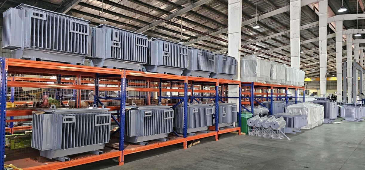
SOTEK Group designs, manufactures, and type-tests a full spectrum of Medium-Voltage Distribution Transformers built to endure aggressive tropical climates, seismic activity, extreme harmonic distortions, and continuous overload operation. Below are our flagship recommended product series engineered for international power grids.
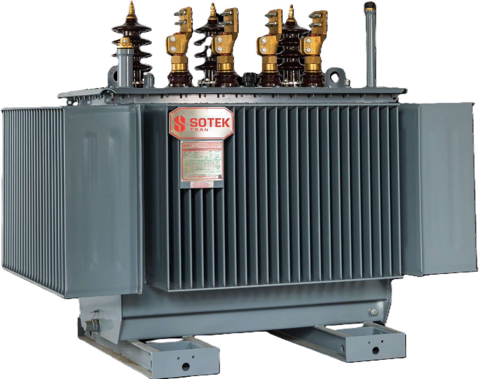 Utility Flagship
 Three-Phase Oil-Immersed MV Transformer
Hermetically sealed corrugated tank design preventing oil oxidation. High-grade CRGO core with step-lap mitered joints for ultra-low excitation current and silent operation.
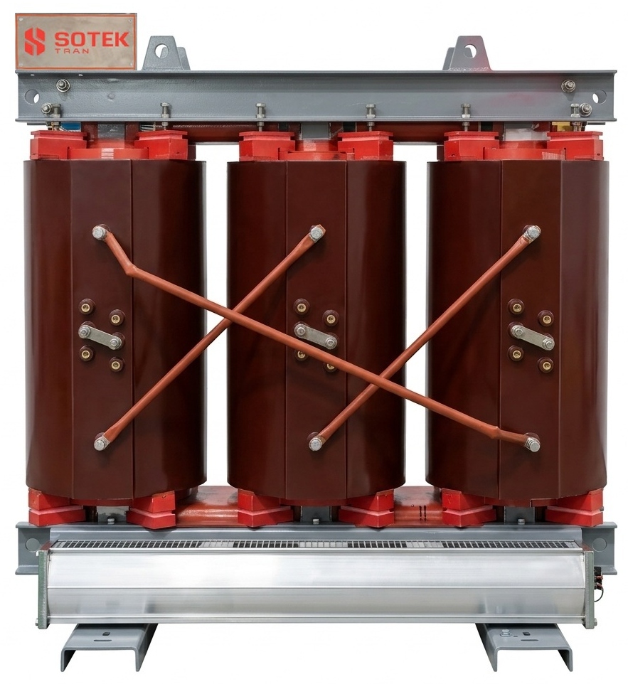 Indoor Safety
 Cast Resin Dry-Type MV Transformer
Vacuum-cast epoxy resin encapsulation with fiberglass reinforcement. Class F (155°C) & Class H (180°C) thermal insulation. Fire-safe, self-extinguishing (F1 rating), zero toxic emissions.
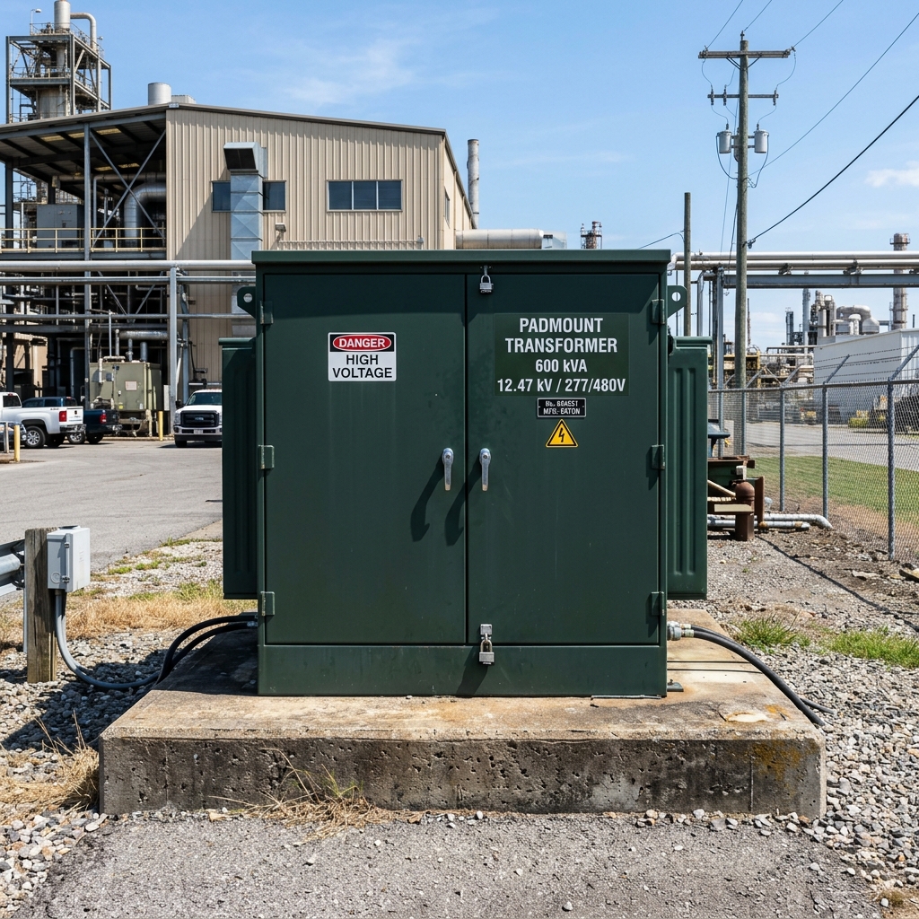 Underground Grid
 Three-Phase Padmount MV Transformer
Tamper-resistant cabinet enclosure with separate HV and LV compartments. Loop-feed or radial-feed configuration, Bay-O-Net current-sensing fuses, and loadbreak switches.
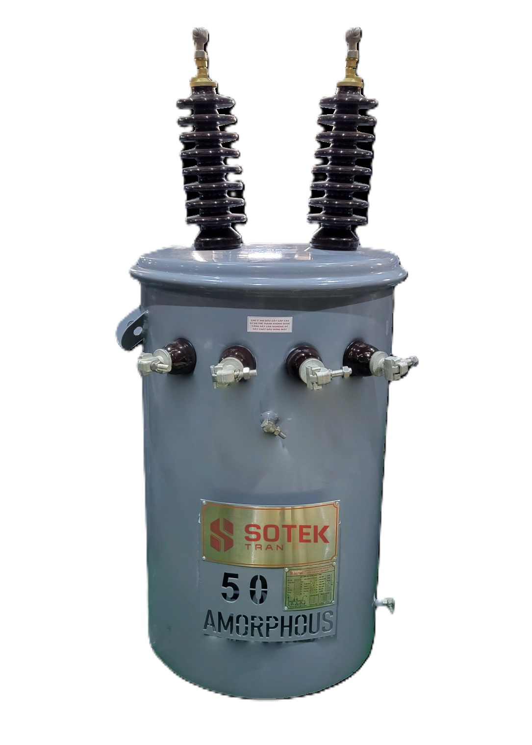
Single-Phase Pole-Mount Transformer
Heavy-duty overhead distribution units designed for rural electrification and decentralized sub-grids. Stainless steel tank option for extreme coastal salt-spray environments.
Green Energy Amorphous Alloy Core MV Transformer
Engineered with Fe-B-Si amorphous metal ribbon, reducing no-load losses (core loss) by up to 75% compared to conventional grain-oriented silicon steel cores.
Renewable Energy Step-Up Transformer
Multi-winding inverter duty transformer designed to handle non-linear solar inverter current harmonics. Available with biodegradable FR3 natural ester fluid for eco-sensitive sites.
Comprehensive Technical Specification Comparison Matrix
To assist electrical system designers and procurement committees in selecting the precise medium-voltage distribution transformer configuration, the following comparative engineering matrix contrasts key operational parameters:
| Transformer Type | Primary Voltage Range | KVA Capacity Range | Cooling & Fluid Medium | Efficiency Standard | Ideal Application Target |
|---|---|---|---|---|---|
| Oil-Immersed Corrugated Tank | 3.6 kV – 35 kV | 50 kVA – 5,000 kVA | Mineral Oil / ONAN | IEC 60076 Tier 2 / DOE 2016 | Utility pole & ground substations, industrial parks |
| Oil-Immersed Conservator Type | 11 kV – 69 kV | 1,000 kVA – 25,000 kVA | Mineral / Ester / ONAF | IEC 60076 / IEEE C57.12.00 | Primary utility substations, heavy industrial plants |
| Cast Resin Dry-Type | 3.6 kV – 35 kV | 50 kVA – 6,300 kVA | Air Natural / ANAN, ANAF | IEC 60076-11 / EN 50588-1 | Indoor high-rises, hospitals, data centers, subways |
| Compartmentalized Padmount | 4.16 kV – 34.5 kV | 75 kVA – 5,000 kVA | Mineral Oil / FR3 Ester | IEEE C57.12.34 / ANSI C57.12.28 | Underground residential & commercial distribution |
| Amorphous Alloy Core | 6.6 kV – 35 kV | 50 kVA – 2,500 kVA | Mineral Oil / FR3 Ester | Ultra-Low Loss (>75% reduction) | Smart grids, solar PV farms, green infrastructure |
Future Procurement Trends in Medium-Voltage Distribution Transformers (2026–2035)
The global market for medium-voltage distribution transformers is undergoing a massive structural transformation. According to market research and utility procurement shifts, several major vectors are dictating how enterprise buyers evaluate and purchase MV transformers over the next decade:
1. Acceleration Toward Bio-Degradable Ester Dielectric Liquids
Environmental regulations and fire safety mandates are driving a rapid global transition from conventional mineral oil to synthetic and natural ester fluids (such as Cargill FR3®). Ester fluids feature a fire flash point exceeding 300°C (K-class rating), rendering them virtually non-flammable. Furthermore, ester liquids are 100% biodegradable within 28 days, preventing soil contamination in environmentally sensitive zones such as solar PV installations near watersheds, coastal industrial hubs, and agricultural grids. SOTEK offers complete FR3-compatible transformer designs with customized thermal insulation systems.
2. Stringent Efficiency Mandates & Carbon Neutrality Pressures
Regulators across North America, the European Union, and Asia-Pacific are enforcing aggressive loss-reduction limits. Compliance with DOE 2026 standards in the US and EU EcoDesign Tier 2 (EN 50588-1) requires transformer manufacturers to lower no-load (core) and load (winding) losses to absolute physical limits. To meet these targets, procurement strategies are pivoting heavily toward laser-domain-refined cold-rolled grain-oriented silicon steel (0.18mm–0.23mm thickness) and amorphous metal alloys. Buyers are increasingly utilizing Total Cost of Ownership (TCO) capitalization formulas during bidding:
Where 'A' and 'B' represent utility capitalization factors per kilowatt over a 30-year lifecycle.
3. Smart Grid Telemetry & Condition Monitoring Integration
The era of passive, unmonitored transformers is ending. Modern medium-voltage distribution transformers are expected to serve as intelligent digital nodes within Smart Grids. Buyers now mandate factory integration of online Dissolved Gas Analysis (DGA) sensors, fiber-optic real-time winding temperature indicators (WTI), digital oil level gauges, and smart tap-changer controllers compatible with IEC 61850 substation automation protocols. SOTEK provides modular IoT sensor packages integrated directly into our MV transformer control cabinets.
4. Supply Chain De-risking & The Rise of Vietnam Manufacturing
Geopolitical tariffs, anti-dumping duties, and severe lead-time bottlenecks from traditional European and American transformer factories (where lead times currently exceed 80 to 120 weeks) have forced global EPC buyers to re-engineer their procurement supply chains. Vietnam has emerged as the premier manufacturing alternative, combining robust steel and copper supply chains, highly skilled electrical engineering talent, favorable trade agreements (CPTPP, EVFTA), and zero-tariff export options to key international markets. SOTEK Group’s state-of-the-art facility in Bac Ninh, Vietnam, stands at the forefront of this global supply chain shift.
Technological Development Trends in MV Distribution Transformer Engineering
Achieving high electrical efficiency, mechanical short-circuit strength, and extended operational lifespans requires continuous breakthroughs in core metallurgy, winding physics, and thermal modeling:
- Laser-Etched CRGO Core Topology: SOTEK utilizes high-permeability, laser-domain-refined CRGO silicon steel. Utilizing 45-degree full mitered step-lap joint cutting on precision Georg (Germany) automated cutting lines reduces no-load losses by up to 22% and lowers transformer acoustic noise levels to under 45 dB.
- Epoxy Vacuum Resin Casting under High Pressure: In dry-type MV transformer production, SOTEK employs advanced Hedrich vacuum casting chambers. Thermal class H epoxy resin mixed with silica filler is injected under high vacuum, eliminating air micro-voids and achieving partial discharge levels below 5 pC (picocoulombs)—significantly superior to the 10 pC limit required by IEC 60076-11.
- Short-Circuit Electrodynamic Withstand Capability: During external grid short-circuit faults, transformer windings experience massive mechanical axial and radial compression forces. SOTEK utilizes computer-simulated Finite Element Analysis (FEA) to design high-rigidity clamping structures, high-density pressboard insulation blocks, and thermally hardened epoxy-coated paper to guarantee zero mechanical deformation under extreme short-circuit stress.
- K-Factor Harmonic Mitigation Winding Engineering: Modern power electronics—such as solar central inverters, variable frequency drives (VFDs), and fast EV chargers—inject high harmonic frequencies (3rd, 5th, 7th, 11th, 13th) into the transformer. SOTEK engineers custom K-Factor rated transformers (K-4, K-13, K-20) utilizing transposed multi-strand rectangular copper conductors to suppress skin effect and proximity losses, preventing destructive thermal overheating.
Why Global Energy Utilities & Engineering Leaders Partner with SOTEK Group
Headquartered in the Tien Son Industrial Zone, Bac Ninh Province, Vietnam, SOTEK Group (SOTEK Transformer Production and Trading Corporation) represents a premier manufacturer of high-reliability medium-voltage distribution and power transformers. Built upon a foundation of strict engineering discipline, ISO 9001:2015 quality management, and ISO 14001:2015 environmental standards, SOTEK delivers uncompromised performance to international utility grids and B2B industrial projects.
18,500 m² Automated Manufacturing Plant
Featuring Georg core cutting lines, automatic foil and wire winding machines, Hedrich vacuum casting chambers, and automated corrugated tank welding lines for precision quality control.
VILAS 1183 Accredited Testing Laboratory
In-house ISO/IEC 17025 certified laboratory capable of performing complete routine, type, and special tests—including lightning impulse tests up to 400 kV and full temperature rise testing.
International Type-Test Validation
Our medium-voltage distribution transformers hold comprehensive type test certification from leading independent testing bodies including ASTA, KEMA, and QUATEST 1 for IEC & IEEE compliance.
EVN & Global Utility Approved
Approved Tier-1 vendor for Electricity Vietnam (EVN across all 5 regional power distribution corporations) and leading international utilities including Aboitiz Power (Philippines).
Global B2B Export Capability
Exporting to over 30 countries across Southeast Asia, Australia, North America, the Middle East, and Africa. Full support for FOB, CIF, or DDP delivery terms.
Rapid Delivery & Custom R&D Engineering
Custom technical drawings within 48 hours and typical lead times of 8 to 14 weeks—offering a dramatic lead-time advantage over traditional Western OEMs.
Frequently Asked Questions: Medium-Voltage Distribution Transformers
Below are detailed, authoritative technical answers to the most common questions submitted by electrical engineers, utility procurement agents, and EPC estimators:
• 50 kVA to 630 kVA: 4.0% to 4.5% %Z
• 800 kVA to 2,500 kVA: 5.75% to 6.0% %Z
• 3,150 kVA to 10,000 kVA: 7.0% to 8.0% %Z
Specifying a higher impedance limits short-circuit fault current levels on downstream switchgear, but increases secondary voltage drop under heavy motor starting loads. SOTEK customizes %Z to meet specific short-circuit calculation requirements.
• ONAN: Oil Natural Air Natural (Standard mineral oil transformer with natural convection radiator cooling).
• ONAF: Oil Natural Air Forced (Fans added to radiators to boost thermal rating by 25% to 33%).
• KNAN: K-class Insulating Liquid Natural Air Natural (Uses non-flammable ester fluid such as FR3 with natural convection).
• KNAF: K-class Insulating Liquid Natural Air Forced (Ester fluid transformer with forced cooling fans).
1. Winding Resistance Measurements (HV & LV).
2. Voltage Ratio & Vector Group Verification.
3. Measurement of No-Load Loss and Exciting Current.
4. Measurement of Load Loss & Short-Circuit Impedance.
5. Applied Voltage Withstand Test (AC High-Pot).
6. Induced Overvoltage Withstand Test.
7. Insulation Resistance (Megger) & Dielectric Oil Breakdown Test.
Type test reports (Lightning Impulse, Temperature Rise, Short-Circuit Withstand) are available upon request.
Ready to Upgrade Your Power Distribution Infrastructure?
Connect directly with SOTEK Group’s senior electrical engineering team. Receive comprehensive CAD dimensional drawings, exact technical datasheets, and competitive factory-direct pricing within 24 hours.