Distribution Transformer Technical Articles, Industry Insights & Grid Updates — SOTEK Group
Transformer Insights &
Technical Articles
Discover in-depth engineering updates, technical specifications, and global power grid solutions from SOTEK.
Cast Resin &
Dry-Type Technology
Learn about advanced insulation classes, fire safety standards, and indoor substation design guidelines.
Padmount &
Substation Engineering
Explore compartmentalized padmount transformer configurations engineered for global power utilities.
How to Choose a Loop Feed Padmount Transformer in 2026
Table of Contents
- Define the Load, Voltage, and Site Requirements
- Choose the Appropriate Loop-Feed Configuration
- Verify Transformer Ratings, Protection, and Applicable Standards
- Assess Enclosure, Safety, and Installation Conditions
- Compare Lifecycle Costs, Serviceability, and Supplier Support
- FAQS
- Conclusion
- Related Posts
Choosing a Loop-feed padmount transformer in 2026 means matching the equipment to the feeder, the site, and the utility’s operating plan. A nameplate alone cannot make that decision. Start with voltage, kVA demand, grounding, available fault current, and the required loop-switching arrangement. Then confirm whether the design needs two load-break ways, a radial feed, or specific sectionalizing options. Small differences matter. A cabinet beside a busy loading dock faces different access, impact, and clearance constraints than one on a quiet utility easement.
Thomas A. Short, author of Electric Power Distribution Handbook, is a recognized voice in distribution engineering. The following is a practical paraphrase, not a verbatim quotation: “Choose switching and protection for the feeder’s real operating needs, not just the transformer’s nameplate.” That principle helps frame the selection. Check bushing interfaces, fuse coordination, enclosure material, corrosion exposure, and expected maintenance access. Ask how crews will isolate one section while keeping the remaining loop energized. Verify details against the utility’s current specifications and the project’s load study.
One detail is easy to miss. A compact cabinet may fit the drawing but leave too little room for safe cable work. Field conditions can be untidy. This guide will help compare ratings, protection, configuration, site requirements, and supplier documentation. It will also flag trade-offs that deserve a second look, including future load growth and replacement access. A careful choice reduces avoidable surprises. It does not remove the need for utility review or qualified engineering judgment.
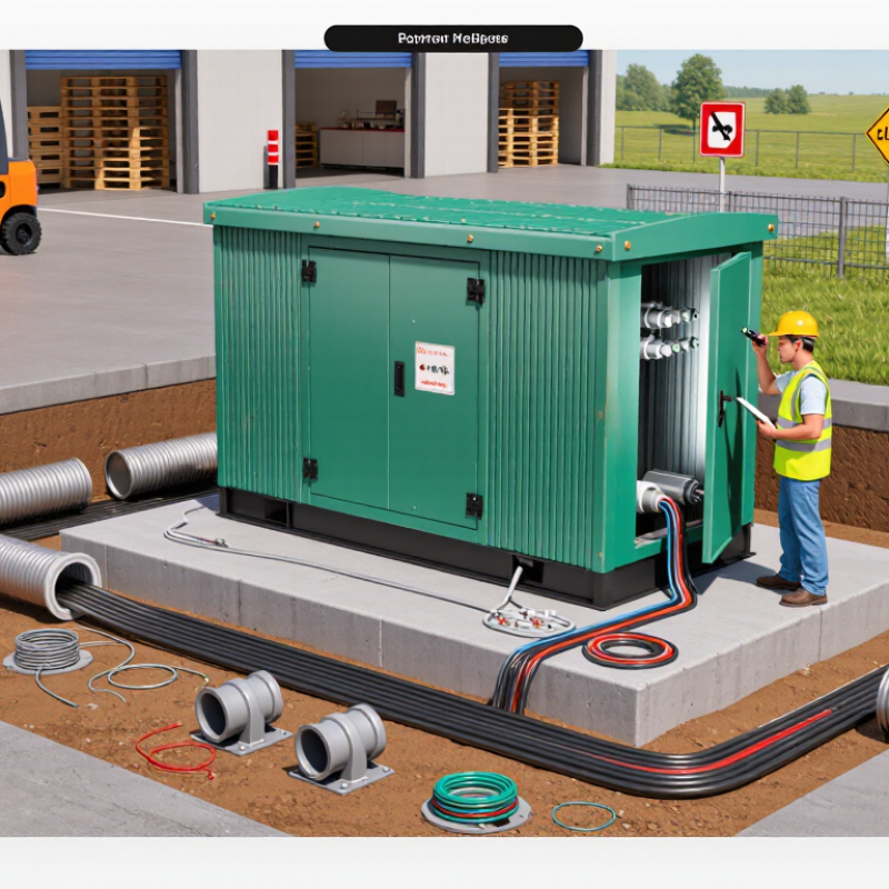
Define the Load, Voltage, and Site Requirements
Start with a measured load profile, not the largest nameplate you can find. Record peak kW, power factor, daily demand, and major motor-starting events. Convert expected demand to kVA, then check normal loading and short-duration peaks with a qualified electrical engineer. Include planned equipment, but question speculative growth; oversized units can add cost and operate inefficiently. A load sheet is rarely perfect.
Match the primary voltage, secondary voltage, frequency, and grounding arrangement to the utility’s available service. Confirm loop-feed configuration, bushing interfaces, and switching needs before ordering. Site details matter too: measure access for delivery and maintenance, required working clearances, cable entry paths, drainage, flood exposure, and corrosive conditions. The U.S. Department of Energy’s 2022 Electric Grid Supply Chain Review reported distribution-transformer lead times rising from 3–6 months in 2019 to 12–30 months in 2022. Accurate specifications can help avoid costly redesigns and delays.
Tips: Ask the utility to confirm service voltage and protection requirements in writing. Photograph the pad, conduit locations, and access route. Recheck clearances against the applicable equipment drawings; field conditions often differ from the plan.
Choose the Appropriate Loop-Feed Configuration
Choosing a loop-feed configuration starts with the utility’s operating plan, not just the transformer’s rating. A loop arrangement provides two primary cable paths, which can help crews isolate a section and restore service from another direction. But two cable paths do not guarantee uninterrupted power. Many systems operate with a normally open point, and switching procedures determine how loads transfer.
Confirm whether the site needs a two-position or multi-position switching arrangement, and verify primary voltage, insulation level, and available fault current with the utility. Check the cable size and elbow requirements, too. A cramped vault or tight bend near the cabinet can make an otherwise suitable layout difficult to install and maintain. That detail matters. Review grounding, protective-device coordination, and the positions of incoming and outgoing cables before approving the one-line diagram. In practice, clear labels and reachable operating handles save time during switching. A tidy drawing can still conceal awkward field access. It is worth walking the proposed cable route with the installer; this step is easy to overlook. Decide whether future load growth or sectionalizing needs justify extra switch positions, rather than adding complexity by default.
Verify Transformer Ratings, Protection, and Applicable Standards
Before selecting a loop-feed padmount transformer, match its nameplate ratings to the actual system. Check kVA, primary and secondary voltages, phase, frequency, impedance, and insulation level. Confirm the required basic impulse insulation level with the utility or project engineer. A mismatch can affect equipment coordination, not just the purchase price.
Protection needs equal scrutiny. Verify the loop-feed switch arrangement, fuse type and rating, and whether the design requires dual-voltage or source-side protection. Compare protective-device curves with available fault current and downstream equipment. Ask how the transformer will be grounded and accessed during maintenance. Small details matter. A fuse that looks adequate on a schedule may not coordinate properly under real system conditions.
Check applicable standards against the installation location and the utility’s current specifications. In North America, IEEE C57-series requirements may apply; IEC or CSA requirements may govern elsewhere. Confirm the exact editions and any local amendments rather than assuming one standard covers every detail. Also review enclosure rating, corrosion protection, temperature rise, and operating conditions such as altitude. A tidy specification sheet can still miss a field constraint. It is worth asking the engineer to revisit assumptions before ordering, especially when load growth or unusual site conditions are expected.
Assess Enclosure, Safety, and Installation Conditions
A loop-feed padmount transformer should fit the site, not just the load schedule. Check the enclosure rating against rain, dust, salt, and possible flooding. Look closely at door seals, hinges, cabinet corrosion protection, and access for lifting equipment. IEEE C57.12.28 provides enclosure-integrity requirements for pad-mounted equipment; ask suppliers for test documentation, not just a rating on a data sheet. Small details matter. A door that opens into a fence can make routine switching awkward and emergency access worse.
Safety and installation conditions need equal attention. Confirm primary voltage, insulation level, available fault current, grounding design, and compatible elbow interfaces with the utility engineer. Keep working clearances and vehicle barriers in the site plan, and check whether cables can enter without tight bends or water traps. The U.S. Energy Information Administration reports that transmission and distribution losses averaged about 5% of electricity transmitted in 2018–2022. That figure is system-wide, not a transformer-selection target, but it underscores why sound installation and equipment coordination matter. A site drawing may look clean while missing a drainage slope or crane approach. Recheck it in the field. That extra review can feel slow, and sometimes the original layout still proves wrong.
How to Choose a Loop Feed Padmount Transformer in 2026 – Assess Enclosure, Safety, and Installation Conditions
| Assessment Dimension | Selection Guidance | Practical Checks | Why It Matters |
|---|---|---|---|
| Loop-feed arrangement | Choose a loop-feed primary arrangement when the circuit must enter and leave the transformer location to continue serving downstream equipment. Confirm the required switching and isolation scheme with the utility or system designer. | Verify the one-line diagram, incoming and outgoing cable routes, phase arrangement, and required primary interfaces. A three-phase loop-feed design commonly uses six primary cable terminations, subject to the equipment configuration. | Correct interface and circuit design support the intended loop operation and prevent mismatches during installation or switching. |
| Primary voltage class | Select a voltage class compatible with the system’s nominal voltage and maximum operating voltage. Common equipment classes include 15 kV, 25 kV, and 35 kV, with exact ratings depending on the system. | Check nominal and maximum system voltage, insulation level, grounding method, and utility requirements. For example, 15 kV-class equipment is commonly rated for systems up to 15.5 kV; confirm the nameplate and applicable design standard. | Voltage-class compatibility is essential for insulation coordination and safe, reliable operation. |
| Transformer capacity | Size the kVA rating from calculated demand, motor starting or other load characteristics, expected growth, and the permitted loading plan. Avoid selecting capacity from connected load alone. | Document present and forecast demand, load profile, ambient conditions, and any required spare capacity. Confirm primary and secondary current ratings against the design. | Appropriate sizing helps limit overheating, unnecessary cost, and avoidable capacity constraints. |
| Primary connectors and switching | Specify connector type and rating to match the cable, system voltage, fault-duty requirements, and operating procedure. 200 A loadbreak interfaces and 600 A deadbreak interfaces are common options in applicable designs; they are not interchangeable by default. | Confirm bushing-well or integral-bushing arrangement, elbow or connector rating, cable conductor size, fault indicators, parking stands, and any required sectionalizing provisions. | Compatible components and a defined switching scheme support safe operation and maintainability. |
| Enclosure and access | Use an outdoor, tamper-resistant pad-mounted enclosure suited to the exposure and access conditions. Check compartment layout, door orientation, corrosion protection, and whether barriers or locks are required. | Review the site’s public access, vehicle exposure, salt or chemical exposure, drainage, and maintenance access. Confirm enclosure construction and finish meet the project and utility specifications. | The enclosure protects energized components and helps reduce unauthorized access and environmental damage. |
| Safety features | Specify dead-front primary construction where required by the design and applicable rules. Include the grounding provisions, protective devices, labels, and operating features required for the installation. | Verify grounding points, pressure-relief provisions, nameplate and warning labels, fusing or other overcurrent protection, and fault-indication requirements. Establish safe work and switching procedures before energization. | Safety depends on correctly specified equipment, installation, operating procedures, and qualified personnel—not on enclosure selection alone. |
| Installation location and clearances | Provide a level, stable foundation with room to deliver, position, inspect, and service the transformer. Maintain the clearances required by the manufacturer, utility, electrical code, and local authority. | Check pad dimensions and loading, cable trench or duct entry, door swing, working space, overhead obstructions, vehicle access, and separation from buildings or other equipment. | Good site planning reduces installation risk and preserves access for inspection, cable work, and future maintenance. |
| Environmental and fluid considerations | Choose the insulating-fluid and containment approach according to fire, environmental, and site requirements. Consider flood exposure, temperature range, and any required spill containment. | Confirm fluid type, environmental permitting, drainage and flood elevation, secondary containment needs, and local restrictions. Do not assume that a particular fluid eliminates the need for site-specific review. | Environmental conditions can affect equipment selection, installation details, permitting, and long-term operating risk. |
| Testing and documentation | Require factory test documentation and installation records appropriate to the project. Confirm that the supplied transformer matches the approved drawings and specification. | Review nameplate data, wiring and connection diagrams, routine test reports, accessory list, and any required field inspection or testing plan before energization. | Complete documentation supports acceptance, troubleshooting, maintenance, and safe future operation. |
Selection note: Ratings, connector arrangements, clearances, protection, and installation requirements vary by system and jurisdiction. Confirm final specifications with the serving utility, qualified electrical engineer, manufacturer documentation, and applicable codes and standards.
Compare Lifecycle Costs, Serviceability, and Supplier Support
For a loop-feed padmount transformer, purchase price is only the visible cost. Compare expected losses, inspection labor, replacement parts, and the cost of an outage across its service life. The U.S. Department of Energy’s 2013 distribution-transformer efficiency rule projected 3.63 quadrillion Btu in energy savings over 30 years. That is a national estimate, not a guarantee for one installation, but it shows why no-load and load losses deserve attention. Ask suppliers for guaranteed loss figures and the assumptions behind them. Check the details.
Serviceability can make a quiet difference. Confirm that crews can reach the compartments, operate the switching arrangement safely, and obtain compatible bushings, fuses, and gaskets. A compact enclosure may fit a site yet leave little room for field work. I would not assume the lowest-loss unit is automatically the best choice; local loading and maintenance capacity matter.
Supplier support also affects lifecycle risk. DOE’s 2022 energy-sector supply-chain assessment reported distribution-transformer lead times stretching from roughly 3–6 months to 12–30 months. Ask about current production schedules, repair options, technical response times, and spare-unit availability in writing. The IEA’s 2023 grids report says annual grid investment must rise above $600 billion by 2030, underscoring pressure on equipment supply. Forecasts change. Verify delivery dates before setting commissioning plans.
FAQS
Record peak kW, power factor, daily demand, and major motor-starting events. Include planned equipment, but question uncertain growth. Load sheets are rarely perfect.
Confirm primary and secondary voltage, frequency, grounding, loop-feed setup, bushing interfaces, and switching needs. Ask the utility to confirm requirements in writing.
Check delivery access, maintenance clearances, cable paths, drainage, flood exposure, and corrosive conditions. Photograph the pad and conduit locations.
Include energy losses, inspections, replacement parts, and outage costs. Ask for guaranteed loss figures and the assumptions behind them. Check the details.
Not necessarily. It may fit the pad but leave little room for crews to work. Verify compartment access and switching arrangements.
Confirm access to compatible bushings, fuses, and gaskets. Ask about repairs, technical response times, and spare-unit availability in writing.
Request a written production schedule and verify the delivery date before planning commissioning. Supply forecasts change, so allow room for uncertainty.
Conclusion
Choosing a Loop-feed padmount transformer in 2026 begins with a clear understanding of the electrical load, primary and secondary voltages, and conditions at the installation site. These requirements help determine the appropriate capacity and loop-feed configuration, including how the transformer will connect to the distribution system and accommodate future demand. Before selecting a unit, verify its ratings, protection features, and compliance with applicable technical standards.
The enclosure and installation plan also deserve careful attention. Consider environmental exposure, access for maintenance, safety clearances, and practical installation constraints. Finally, compare options over their full service life rather than focusing only on the initial purchase price. Maintenance needs, ease of servicing, expected operating costs, and the quality of supplier support can all affect long-term value and reliability.

Blog Tags: