Distribution Transformer Technical Articles, Industry Insights & Grid Updates — SOTEK Group
Transformer Insights &
Technical Articles
Discover in-depth engineering updates, technical specifications, and global power grid solutions from SOTEK.
Cast Resin &
Dry-Type Technology
Learn about advanced insulation classes, fire safety standards, and indoor substation design guidelines.
Padmount &
Substation Engineering
Explore compartmentalized padmount transformer configurations engineered for global power utilities.
Why Choose a Solar Farm Transformer for Your Project?
Table of Contents
- What Is a Solar Farm Transformer and How Does It Work?
- How Solar Farm Transformers Connect Panels to the Power Grid
- Key Technical Features of Solar Farm Transformers
- Why Transformer Selection Affects Solar Farm Performance
- How to Choose the Right Transformer for Your Project
- FAQS
- Conclusion
- Related Posts
A solar farm transformer does more than raise voltage before electricity enters the grid. It manages heat, electrical stress, harmonics, and changing power levels across long operating hours. At sunrise, its workload rises gradually. By midday, intense solar radiation can push cooling systems harder. At sunset, the load falls again.
Power-system specialist Dr. J. C. Das explains the principle clearly: “Transformer design begins with the system duty, not the nameplate alone.” That insight matters when choosing equipment for a utility-scale project. A suitable Solar farm transformer should match the plant’s inverter output, collection voltage, grounding method, cooling conditions, and expected expansion. It should also tolerate frequent load variation without sacrificing insulation life or efficiency.
Small details become expensive problems. Poor ventilation may increase winding temperature. Weak surge protection can expose insulation to lightning impulses. An unsuitable impedance value may create voltage instability between transformer units. These risks deserve attention before procurement, not after commissioning.
Field experience also shows that the cheapest transformer is rarely the cheapest long-term choice. Lower purchase costs can hide higher losses, difficult maintenance, or limited spare-part availability. Still, no design is perfect. Weather data may be incomplete, future capacity may change, and actual inverter behavior can differ from early assumptions. Engineers must question their own calculations.
Choosing a Solar farm transformer means balancing efficiency, resilience, service access, and total ownership cost. The right decision supports safer operation, steadier grid delivery, and stronger project performance over decades.
What Is a Solar Farm Transformer and How Does It Work?
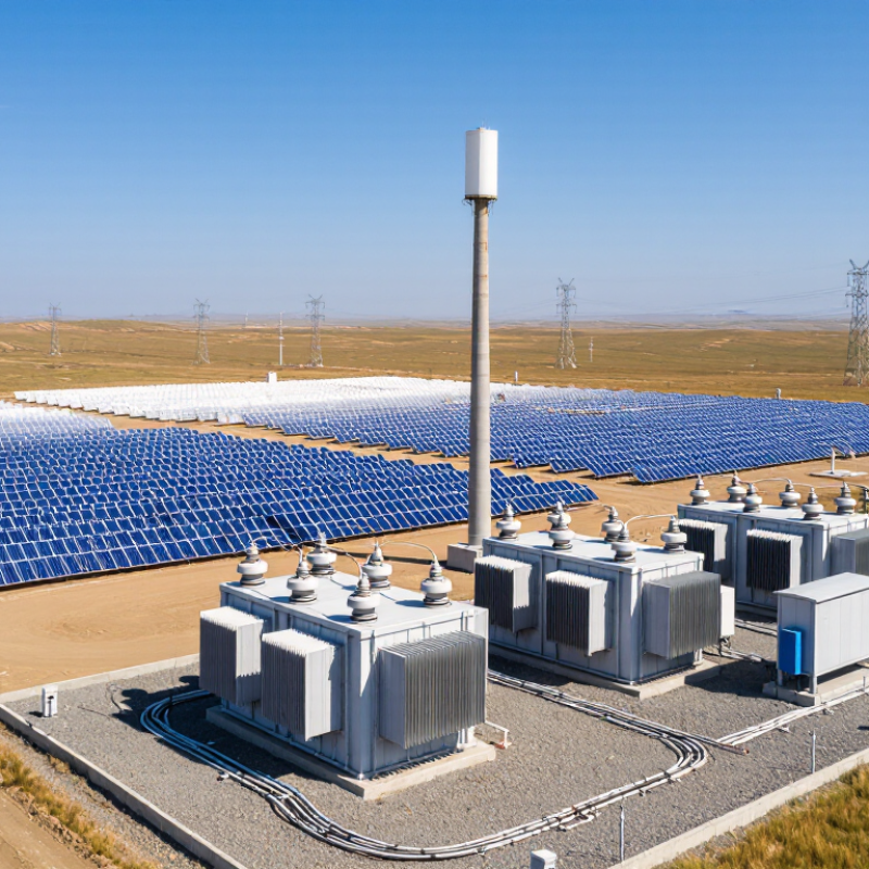
A solar farm transformer connects the inverter system to the electrical grid. Solar panels produce direct current, while inverters convert it into alternating current. The transformer then increases the voltage for efficient transmission across collection lines. This process reduces current and limits energy losses over long distances.
Inside the unit, copper windings surround a magnetic steel core. Alternating current creates a changing magnetic field, which transfers energy between the windings. A lower-voltage winding receives power from the inverter. A higher-voltage winding sends power toward the substation. Cooling equipment controls heat, while sensors track temperature, oil condition, and unusual electrical activity. During field inspections, technicians may notice a steady hum, warm enclosures, or dust around cable terminations. These details matter.
Choosing the right transformer requires more than matching the farm’s peak capacity. Engineers examine inverter output, voltage levels, harmonics, weather, installation height, and expected daily load changes. A unit with excessive capacity can increase costs and operate inefficiently at light loads. An undersized unit may overheat during strong sunlight. Protection systems should respond to faults without causing unnecessary shutdowns. Maintenance access also deserves attention. A design can appear efficient on paper, yet become difficult to service after installation. I have found that practical layouts often protect reliability better than impressive specifications alone. Even small temperature trends can reveal a developing problem before production is affected.
How Solar Farm Transformers Connect Panels to the Power Grid
A solar farm transformer is the working bridge between photovoltaic panels and the power grid. Panels generate direct current, while inverters convert it into usable alternating current. The transformer then raises the inverter’s voltage for efficient collection. This step matters. Higher voltage reduces current and limits energy loss across long cables. At medium voltage, several transformer outputs can join within the collection network. Underground or overhead cables carry this power toward the project substation. There, another transformer may increase voltage again for grid transmission.
The connection must match grid requirements, not just panel capacity. Engineers check voltage, frequency, grounding, fault levels, and protection settings. They also consider heat, dust, moisture, and uneven sunlight across the site. Oil temperature and winding temperature need regular monitoring. Small details matter. Poor cable routing can increase losses and complicate maintenance. A transformer with extra capacity may handle future expansion, but it can raise project costs. A smaller unit may appear efficient, yet it could face stress during peak production. Perfect design is unrealistic. Field conditions often challenge calculations. Careful load studies, clear protection coordination, and accessible inspection points make the connection more dependable. Even a well-designed system deserves review after commissioning.
Key Technical Features of Solar Farm Transformers
Why Choose a Solar Farm Transformer for Your Project?
Key Technical Features of Solar Farm Transformers
A solar farm transformer must handle changing output, high temperatures, and frequent load variation. Its voltage ratio should match the inverter and grid connection precisely. Incorrect selection can increase losses and create unstable operating conditions. That detail matters. Engineers usually review rated power, insulation level, short-circuit strength, and cooling capacity before approval. In field commissioning, technicians should verify winding resistance, insulation performance, protection settings, and grounding connections. Small testing errors can become expensive failures.
Modern units may use oil-filled or dry-type construction, depending on fire protection, space, and maintenance requirements. Low-load and full-load losses deserve equal attention because solar output changes throughout the day. Harmonic heating also needs review when power electronics are connected. A suitable tap changer can support voltage control, but it requires careful coordination with the grid. Online temperature, oil level, and partial-discharge monitoring can provide earlier warnings. Still, sensors are not a substitute for scheduled inspections.
Tips: Compare actual inverter data with the transformer datasheet, not only the headline kVA rating. Check ambient temperature, altitude, cable length, and expected future expansion. Ask for routine and type-test records from qualified manufacturers. Leave practical access around the enclosure. It seems minor, but blocked ventilation can shorten equipment life. Recheck assumptions after one operating season; field conditions often differ from design models.
Why Transformer Selection Affects Solar Farm Performance
Why Choose a Solar Farm Transformer for Your Project?
Why Transformer Selection Affects Solar Farm Performance
A solar farm transformer does more than raise voltage for grid delivery. Its design influences energy losses, voltage stability, heat management, and daily operating reliability. A poorly matched transformer can waste power during peak sunlight. That loss may appear small, but it grows across thousands of operating hours.
Engineers should examine rated capacity, voltage ratio, insulation class, cooling method, impedance, and harmonic tolerance. Inverter output is not perfectly smooth. Harmonics can increase heating and shorten insulation life. Outdoor conditions matter too. Dust, humidity, salt air, and rapid temperature changes can challenge enclosure performance. In field evaluations, a transformer with extra capacity often handles expansion better. However, oversizing can raise costs and reduce efficiency during light-load periods. There is no perfect choice.
Tips: Compare the transformer with the inverter’s real output profile, not only its nameplate rating. Check expected ambient temperatures and site elevation. Confirm protection settings with the utility and project engineer. Leave safe access for inspection. Small details matter.
Routine testing should include insulation checks, temperature review, oil analysis where applicable, and connection inspections. Reliable records help reveal gradual changes before failures occur. Some project teams focus heavily on purchase price. That approach deserves reconsideration. A slightly higher initial cost may support lower losses and fewer service interruptions over the farm’s operating life.
How to Choose the Right Transformer for Your Project
Choosing the right transformer begins with the solar farm’s actual operating conditions, not its nameplate capacity. Review the inverter output, collection voltage, expected load profile, and future expansion plans. A transformer sized only for today may restrict tomorrow’s production. Oversizing also deserves caution. It can increase purchase costs and create inefficient operation during low-generation periods.
Site conditions matter just as much. Check ambient temperature, altitude, dust, humidity, flooding risk, and available maintenance access. Dry-type units may suit enclosed areas, while oil-immersed transformers can provide efficient cooling for larger installations. However, oil containment and fire protection require careful engineering. Grounding, insulation coordination, and short-circuit withstand ratings should match the entire collection system.
Harmonics need attention.
Inverter-based generation can affect transformer heating and losses. Ask for test data that reflects the intended inverter configuration, rather than relying only on standard ratings. Confirm compliance with applicable electrical codes and project specifications. Protection settings should coordinate with medium-voltage equipment and utility requirements. Field engineers should also inspect cable routes, ventilation, and termination spaces before final selection. These details are easy to underestimate. A technically suitable transformer may still become difficult to service if access is poor. Recheck the assumptions. Weather records, load forecasts, and maintenance plans can change before construction begins.
FAQS
It raises inverter voltage before electricity enters the collection network. Higher voltage reduces current and cable losses. It acts as a bridge.
Nameplate capacity may not show actual production patterns. A small unit can face stress during strong sunlight. Oversizing can waste money during low-generation periods.
Engineers should check temperature, altitude, dust, humidity, flooding risk, and maintenance access. Salt air can also challenge outdoor equipment. Conditions change.
Inverter output may contain harmonics that increase heating and losses. Over time, this can shorten insulation life. Standard ratings may not tell the whole story.
Dry-type units may suit enclosed spaces. Oil-immersed units can cool larger installations efficiently. Oil containment and fire protection need careful planning.
Protection settings should coordinate with medium-voltage equipment and utility requirements. Engineers must review grounding, insulation coordination, and short-circuit withstand ratings.
Teams can inspect connections, review temperatures, and test insulation regularly. Oil analysis may apply to oil-filled units. Clear records reveal gradual changes.
Extra capacity may support additional panels later. However, it increases purchase costs and may reduce light-load efficiency. Future plans deserve another review.
Poor routing can increase losses and complicate repairs. Accessible inspection points make maintenance safer and quicker. A technically suitable unit can still be inconvenient.
Conclusion
A solar farm transformer is a critical electrical device that converts the variable voltage produced by solar panels into a level suitable for collection, transmission, and delivery to the power grid. It supports the complete energy pathway by connecting panel arrays, inverters, and grid infrastructure while helping manage voltage differences and electrical losses. Understanding how this process works is essential for designing a reliable and efficient solar energy project.
Choosing the right Solar farm transformer can directly affect system performance, safety, operating stability, and long-term maintenance requirements. Important technical features may include suitable power capacity, voltage ratings, insulation, cooling methods, efficiency, environmental resistance, and compatibility with the project’s inverter and grid connection. Project owners should evaluate site conditions, expected energy output, expansion plans, installation requirements, and applicable electrical standards before making a selection. A properly matched transformer helps improve energy delivery, reduce downtime, and support consistent solar farm operation throughout its service life.

Blog Tags: