Distribution Transformer Technical Articles, Industry Insights & Grid Updates — SOTEK Group
Featured Industrial & Power Transformers
Explore our custom OEM and ODM distribution, isolation, and current monitoring transformer configurations engineered for global power grids and industrial substations.
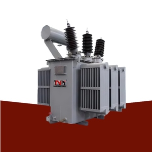
69kV 33kV ONAN Oil Immersed Power Transformer
High-capacity step-down oil-immersed power transformer with copper windings for grid utility substations.
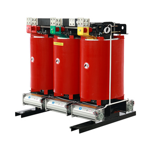
3-Phase Dry Type Industrial Isolation Transformer
Heavy-duty cast resin dry type isolation transformer designed for harmonic suppression and industrial safety.
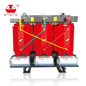
10/11kV Step Down Dry Type Transformer
Equipped with automated cross-flow forced cooling fans, high thermal shock resistance, and zero partial discharge core.
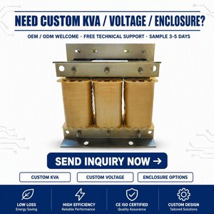
35kV to 380V Low-Frequency Step Down Transformer
Compact medium-voltage dry transformer certified for primary step-down power conversion in commercial complexes.
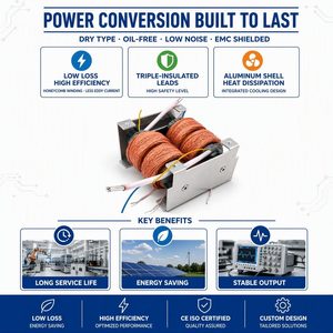
Single Phase High Frequency Custom OEM Transformer
Specialized honeycomb winding structure for extreme isolation, low noise, and minimal high-frequency interference.
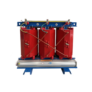
3-Phase Cast Resin Power Transformer 10KV 35KV
Flame-retardant, self-extinguishing cast resin unit optimized for mining, renewable plants, and indoor substations.
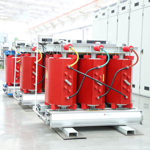
630KVA 20kV to 415V Low Loss Dry Type Transformer
Engineered with high-grade CRGO silicon steel for maximum efficiency and minimized operational thermal load.
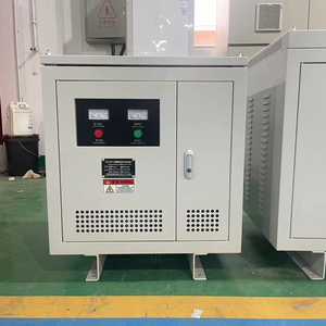
IEC60076 Isolation Transformer 440V to 220V
Fully compliant with international IEC and ISO standards for commercial, industrial step-down and voltage matching.
Leading Custom OEM Current Transformer Manufacturing Partner
In modern power distribution networks, smart grids, and industrial energy management systems, accurate electrical parameter measurement is fundamental. As an established Custom OEM Current Transformer Manufacturer & Supplier, our company operates at the intersection of precision electromagnetic engineering, state-of-the-art material science, and automated manufacturing. Operating across fully ISO 9001:2015 and ISO 14001:2015 certified facilities spanning over 18,500 square meters, we provide customized OEM/ODM instrument transformer solutions designed to satisfy rigorous global standards, including IEC 61869-2, IEEE C57.13, and ANSI specifications.
Current transformers (CTs) serve as the vital sensory apparatus of the electrical grid, stepping down high primary currents to standardized secondary values (typically 5A or 1A) for metering instruments, digital protective relays, and energy management systems. Delivering error-free ratio performance, high phase displacement control, and high short-circuit withstand thermal capabilities ($I_{th}$) requires uncompromising manufacturing discipline. From high-permeability Nanocrystalline cores to precision automated toroidal winding systems, our engineering capability ensures every OEM unit meets zero-defect thresholds prior to installation.
Engineering Blueprint: Precision OEM Current Transformer Design
An in-depth analysis of magnetic core selection, accuracy class physics, protective vs. metering requirements, and insulation technology for power system engineers.
1. Electromagnetic Core Material Metallurgy & Permeability Optimization
The metrological precision and saturation limits of a Current Transformer depend entirely on the ferromagnetic characteristics of its underlying magnetic core. As a premier OEM supplier, we tailor the core material geometry and alloy composition according to the specified operating intent:
Nanocrystalline Ribbon Cores
Featuring initial permeability ($\mu_i$) exceeding 80,000 to 100,000, ultrafine grain nanocrystalline alloys (Fe-Cu-Nb-Si-B) provide extraordinarily low coercive force and minimal core loss. This is the optimal material choice for Class 0.2S and Class 0.1 revenue-grade metering CTs operating over wide dynamic load ranges (1% to 120% of rated current).
Cold-Rolled Grain-Oriented (CRGO) Steel
Utilizing high-permeability silicon steel grades (such as M4, M3, or Hi-B domain-refined steels), CRGO cores deliver exceptionally high flux saturation density ($B_s \approx 1.9 \text{ to } 2.05 \text{ Tesla}$). Designed specifically for 5P10, 5P20, and 10P20 protective class current transformers requiring high Accuracy Limit Factors (ALF).
Permalloy (Nickel-Iron Alloys)
Composed of 78% to 80% Nickel content (Mu-Metal), Permalloy exhibits high magnetic permeability at near-zero magnetic excitation currents. Ideal for low-ratio OEM CTs, micro-current sensors, and residual zero-sequence earth fault current monitoring units.
2. Accuracy Class Specification Standard (IEC 61869-2 vs. IEEE C57.13)
Understanding the mathematical margins of ratio error ($\varepsilon$) and phase displacement ($\delta$) is critical when issuing OEM custom fabrication requests. Below is a structural engineering comparison matrix for B2B procurement evaluation:
| Standard | Classification Type | Accuracy Class | Ratio Error at $100\% I_n$ | Phase Shift ($\delta$) at $100\% I_n$ | Primary Application Area |
|---|---|---|---|---|---|
| IEC 61869-2 | Revenue Metering | Class 0.2S | ±0.2% | ±10 minutes (0.3 mrad) | Grid Interconnection, Commercial Billing Meters |
| IEC 61869-2 | Industrial Metering | Class 0.5 | ±0.5% | ±30 minutes (0.9 mrad) | Switchboard Ammeters, SCADA Monitoring |
| IEC 61869-2 | Protection Relay | 5P20 / 10P20 | ±1.0% / ±3.0% | ±60 minutes / N/A | Feeder Protection Relays, Short-Circuit Trip |
| IEEE C57.13 | ANSI Metering | 0.3 B-0.9 | ±0.3% | ±0.3% Transformer Correction | North American Utility Tariff Metering |
| IEEE C57.13 | ANSI Relay Protection | C800 / C400 | ±10.0% at $20 \times I_n$ | Calculated Knee-Point Voltage | Differential Protection, Heavy Substation Bus |
3. Advanced Cast Resin Solid Insulation & Environmental Protection
For medium-voltage (MV) and low-voltage (LV) equipment installations, internal insulation failure is the leading cause of field outages. Our factory utilizes high-vacuum epoxy resin casting chambers (Hedrich technology) to eliminate micro-voids and partial discharge (PD). Every OEM cast resin current transformer guarantees a partial discharge level below **5 pico-Coulombs (5 pC)** at $1.2 \times U_m$, far exceeding standard market benchmarks.
Outdoor units feature specialized Hydrophobic Cycloaliphatic Epoxy (HCEP) resins or high-grade silicone rubber housings capable of resisting UV radiation, salt-spray corrosion (Class C5-M environments), surface tracking, and chemical pollution in harsh desert or coastal energy installations.
Enterprise OEM Customization & Manufacturing Superiority
We eliminate supply chain risks by pairing custom engineering flexibility with mass-production industrial capacity.
100% Tailored Mechanical Form Factors
Whether your application requires split-core retrofit structures, ring-type busbar units, rectangular window dimensions for heavy copper busbars, or compact PCB-mount micro CTs, our engineering design team delivers 3D CAD/STEP models within 24-48 hours.
ISO/IEC 17025 Certified Routine & Type Testing
Every single OEM current transformer leaves our production line with verified individual test reports. Our internal testing capabilities include lightning impulse withstand testing (up to 300kV BIL), short-circuit thermal power tests, primary injection testing, and magnetic hysteresis curve plotting.
Automated Precision Coil Winding
We deploy high-speed multi-axis CNC toroidal winding machines that ensure uniform wire tension, tight layer insulation interleaving, and absolute zero variation in turn counts. This guarantees consistent phase angle response across entire production batches.
Global B2B Supply Chain Compliance
With extensive export experience supplying tier-1 switchgear builders, EV charger manufacturers, and utility contractors across North America, Europe, Southeast Asia, and Australia, we guarantee full compliance with RoHS, REACH, CE, UL, and KEMA requirements.
Scalable Volume Production
Our modular production lines seamlessly adapt from low-volume custom prototyping orders to high-capacity monthly runs of over 100,000 units, providing stable lead times and competitive factory-direct OEM pricing structures.
Dedicated Application Support
Assigning a dedicated senior electromagnetic engineer to every OEM account, we assist your engineering team through burden calculations, saturation risk assessments, thermal rise simulation, and secondary protection circuit design.
Future Technology Trends in Current Transformer Procurement
How smart grids, renewable energy, and digital substations are reshaping current sensor specifications.
1. Transition to Low-Power Instrument Transformers (LPITs) & Rogowski Coils
With the rapid migration towards digital substations compliant with IEC 61859-9-2 process bus standards, traditional 5A/1A high-power secondary outputs are increasingly replaced by Low-Power Voltage Outputs (e.g., 225mV, 3.33V) or optical signals. OEM buyers are prioritizing non-saturating **Rogowski coils** for wide dynamic current measurement in compact smart switchgear and EV fast-charging infrastructures.
2. Wideband Frequency Response for Renewable Energy Inverters
Solar PV inverters, wind turbine converters, and battery energy storage systems (BESS) inject high-frequency switching harmonics into the grid. Future-proof current transformers must exhibit flat amplitude-frequency responses up to 50th harmonic orders ($2.5 \text{ kHz to } 10 \text{ kHz}$) without experiencing excessive core eddy-current heating.
3. Miniaturization and High Thermal Endurance for EV Charging
Megawatt DC fast-charging stations demand ultra-compact split-core and solid-core current transformers capable of continuous operation at elevated ambient temperatures ($+105^\circ\text{C}$). Advanced Class H ($180^\circ\text{C}$) insulation materials and high-efficiency core geometry are becoming non-negotiable OEM requirements.
B2B Engineering RFQ Checklist for Custom OEM CTs
To accelerate custom design, prototyping, and price quotation, please provide the following parameters when submitting your engineering inquiry:
- Primary Rated Current ($I_{pn}$): e.g., 5A to 10,000A
- Secondary Rated Output ($I_{sn}$ / $V_{sn}$): e.g., 5A, 1A, 3.33V, 225mV, 4-20mA
- Rated Burden / Load (VA): e.g., 2.5VA, 5VA, 15VA, 30VA
- Accuracy Class Requirement: e.g., Class 0.2S, Class 0.5, 5P20, C800
- Operating System Voltage ($U_m$): e.g., 0.66kV, 3.3kV, 11kV, 33kV, 69kV
- Physical Dimension Envelope: Window inner diameter, maximum outer dimensions, mounting style
- Short-Time Thermal Current ($I_{th}$): e.g., $40\text{kA} / 1\text{s}$, $60 \times I_n$
- Operating Environment: Indoor/Outdoor, Temperature Range (e.g., $-40^\circ\text{C} \text{ to } +85^\circ\text{C}$), IP Rating
Frequently Asked Questions (FAQ)
Common technical questions regarding custom OEM current transformer design, manufacturing, and global ordering procedures.
Request a Custom OEM Current Transformer Engineering Quote
Partner with an industry-leading transformer manufacturer. Contact our application engineering team today to analyze your specifications, request 3D models, or receive competitive volume pricing.
Send an Inquiry