Distribution Transformer Technical Articles, Industry Insights & Grid Updates — SOTEK Group
Featured Industrial & Utility-Grade Transformers
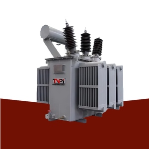
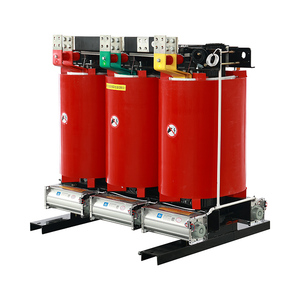
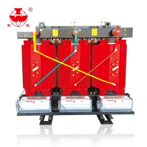
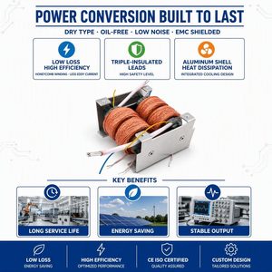
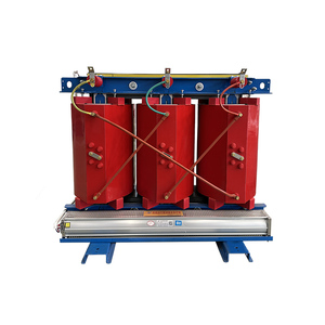
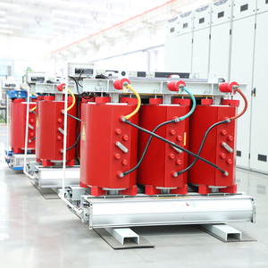
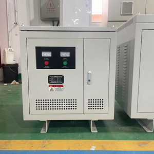
Explore our flagship series of oil-immersed, cast resin dry-type, and step-down substation transformers engineered with high-permeability amorphous ribbons and precision CRGO core geometries.
The Physics of Amorphous Metal Ribbons vs. CRGO Silicon Steel
Understanding atomic structural disorder, magnetic domain mechanics, and hysteresis loss suppression in iron-based metallic glass (Fe-Si-B) alloys.
Non-Crystalline Atomic Layout
Unlike conventional Cold-Rolled Grain-Oriented (CRGO) steel which exhibits a structured crystalline lattice, amorphous metal alloys are rapidly solidified at over 1,000,000°C per second. This ultra-fast melt-spinning cooling process freezes liquid iron-silicon-boron (Fe-Si-B) atoms into a random, glass-like atomic state, completely eliminating grain boundaries and magnetocrystalline anisotropy.
Ultralow Coercive Force & Hysteresis
Because there are no microscopic grain boundaries or lattice defect barriers to hinder magnetic domain wall motion, amorphous cores exhibit extremely low coercive force (Hc < 2 A/m). When subjected to alternating 50Hz/60Hz electromagnetic excitation, the energy required to reverse magnetic alignment is a fraction of that required by M4 or 23ZH085 silicon steel grades.
Micro-Thin Ribbon Eddy Suppression
Eddy current losses are proportional to the square of the material's thickness ($P_e \propto t^2$). Standard CRGO laminations range between 0.18mm and 0.30mm, whereas amorphous alloy ribbons are produced at an ultra-thin 25 to 30 microns (0.025–0.030mm). Coupled with higher electrical resistivity (137 µΩ·cm vs 45 µΩ·cm in CRGO), eddy currents are virtually suppressed.
Comprehensive Material Benchmark: Fe-Based Amorphous Ribbon vs. CRGO Steel
| Physical & Electromagnetic Parameter | Amorphous Ribbon (Fe-Si-B) | High-Permeability CRGO (30ZH120) | Conventional Silicon Steel (M4) |
|---|---|---|---|
| Atomic Structure | Amorphous (Glassy Metallic) | Crystalline Grain-Oriented | Crystalline Grain-Oriented |
| Material Ribbon/Sheet Thickness | 0.025 mm (25 µm) | 0.23 mm – 0.30 mm | 0.27 mm – 0.35 mm |
| Saturation Magnetic Flux Density ($B_s$) | 1.56 Tesla | 1.90 – 1.95 Tesla | 2.03 Tesla |
| Specific Electrical Resistivity | 137 µΩ·cm | 48 µΩ·cm | 45 µΩ·cm |
| Specific Core Loss @ 1.5T, 50Hz | 0.20 – 0.28 W/kg | 0.85 – 0.95 W/kg | 1.10 – 1.30 W/kg |
| No-Load Loss Reduction Potential | 70% to 80% Savings | Baseline Reference | +15% Higher Loss |
| Annealing Temperature Environment | 360°C – 390°C (Inert Gas + Magnetic Field) | 800°C – 850°C | 800°C – 830°C |
Future Procurement Trends for Amorphous Core Transformers (2025–2035)
Global electrical utilities, renewable energy developers, and commercial infrastructure projects are executing aggressive supply chain shifts toward amorphous alloy power distribution transformers.
1. Tightening Energy Efficiency Directives (DOE 2026 & EU EcoDesign Tier 3)
Regulatory bodies across North America, Europe, and Asia-Pacific are enforcing stringent minimum energy performance standards (MEPS). The United States Department of Energy (DOE) 2026 distribution transformer rules and EU EcoDesign directives mandate loss reductions that push CRGO silicon steel to its physical limit. Amorphous core transformers naturally satisfy and exceed Tier 3 eco-efficiency targets, making them the preferred choice for future-proof utility tenders.
2. Capitalizing Total Cost of Ownership (TCO) Evaluation Models
Modern B2B procurement officers no longer buy transformers based solely on initial capital expenditure (CAPEX). Utilities apply Total Cost of Ownership (TCO) formulas: $TCO = CAPEX + (A \times P_0) + (B \times P_k)$, where $P_0$ represents no-load loss and $A$ represents the capitalized monetary value per watt of continuous loss over 30 years (often $5 to $12 per watt). Because no-load loss occurs 24/7/365 regardless of grid load, an amorphous core's 75% reduction yields a full payback on CAPEX premium within 2 to 4 years.
3. Integration with Solar PV, Wind Farms & EV Supercharging Networks
Renewable generation assets and EV charging hubs experience extreme load variance—often idling during non-peak solar/wind hours or overnight. During light-load periods, no-load loss dominates transformer inefficiency. Amorphous core step-up and step-down transformers prevent massive standby energy dissipation, maximizing net energy export back to the transmission grid and improving overall project Internal Rate of Return (IRR).
China Enterprise Advantage: SOTEK & YAWEI Manufacturing Capabilities
Combining metallurgical science with precision automated assembly lines to deliver world-class OEM/ODM distribution transformers for global EPC contractors.
Automated Ribbon Cutting & Core Stacking
Amorphous ribbons are extremely thin and brittle post-annealing. Our factory utilizes state-of-the-art automated laser-shearing lines and servo-controlled rectangular core wrapping machinery. This eliminates micro-fractures, guarantees uniform core cross-sections, and maintains exact magnetic domain integrity throughout mass production.
Inert Atmosphere Magnetic Annealing
Core stress relief is critical. Our plant houses specialized sealed annealing furnaces operating under high-purity argon gas atmospheres with applied DC magnetic fields (1500–2000 A/m). This process relieves internal ribbon stress, aligns atomic magnetic domains along the optimal flux path, and dramatically minimizes magnetostriction noise.
Short-Circuit Mechanical Reinforcement
Due to the non-rigid structure of amorphous alloy cores, mechanical support relies on advanced coil encapsulation. We engineer rectangular epoxy-cast copper/aluminum windings with high-density pressboard spacers and heavy-duty steel end-clamps, ensuring compliance with IEC 60076-5 short-circuit electrodynamic withstand requirements.
Rigorous ISO & KEMA Type Testing
Every production batch undergoes full Factory Acceptance Testing (FAT) in our ISO/IEC 17025 accredited laboratory. Tests include lightning impulse withstand, partial discharge measurement (< 5 pC), temperature rise, winding resistance, acoustic sound level testing, and dissolved gas analysis (DGA) for liquid-immersed units.
Frequently Asked Procurement & Engineering Questions
Key technical considerations for power distribution engineers, utility tender boards, and industrial procurement managers.
Q: How does an amorphous core transformer achieve 70–80% lower no-load loss compared to CRGO transformers?
No-load loss consists of hysteresis loss and eddy current loss. Amorphous metal ribbons lack a crystalline lattice structure, allowing magnetic domains to flip with almost zero frictional resistance (slashing hysteresis loss). Furthermore, because the amorphous ribbon is only 0.025mm thick (1/10th of silicon steel) and possesses high electrical resistivity, eddy currents within the core are virtually eliminated.
Q: Are amorphous core transformers more noisy than standard silicon steel transformers?
Historically, early-generation amorphous cores suffered from higher magnetostriction noise. However, modern China manufacturing processes incorporate three-phase five-column rectangular core geometries, specialized magnetic field thermal annealing, and high-damping silicone vibration pads. Today’s amorphous transformers easily meet IEC 60076-10 and NEMA ST-20 acoustic standards, operating well under 50 dB(A) for dry-type and 45 dB(A) for oil-immersed units.
Q: How do amorphous transformers withstand electrodynamic short-circuit forces?
Since amorphous alloy ribbons cannot bear heavy mechanical load structural stress, the mechanical strength of the transformer is completely transferred to the outer coil winding structure. Our engineering design uses rigid epoxy-impregnated rectangular coil frames, high-tensile clamping plates, and solid phase insulation. All units are short-circuit verified according to IEC 60076-5 and IEEE C57.12.90 standards.
Q: What is the typical ROI and payback period when choosing amorphous over CRGO?
While an amorphous core transformer typically carries a 15% to 25% higher initial CAPEX compared to a standard CRGO unit, the continuous 24/7 energy savings from an 75% drop in no-load losses yields substantial operational savings. Depending on regional electricity tariffs ($0.08 to $0.20 per kWh) and utility TCO capitalization formulas, the average payback period ranges between 1.8 and 4 years over a 30-year operational lifespan.
Q: Can amorphous transformers be customized for high-voltage substation applications?
Yes. We design and manufacture both oil-immersed ONAN/ONAF distribution power transformers up to 69kV / 30MVA and cast resin dry-type isolation transformers up to 35kV class. Custom options include On-Load Tap Changers (OLTC), De-Energized Tap Changers (DETC), K-factor ratings for harmonic environments, and severe ambient enclosures (IP54 / NEMA 3R / C5-M marine anti-corrosion coating).
Q: What lead times and shipping packaging can international buyers expect?
Standard production lead time is 25 to 40 days upon drawing approval. All transformers are packaged in heavy-duty sea-worthy vacuum-sealed foil barriers with desiccant packs inside IP-rated reinforced wooden crates to prevent moisture ingress, oxidation, or vibration damage during transoceanic transit.
Partner with China's Premier Amorphous Core Manufacturer
Request detailed technical datasheets, full CAD dimensional drawings, certified type test reports, and customized OEM/ODM factory-direct quotations for your utility or industrial project.
Get Catalog