Distribution Transformer Technical Articles, Industry Insights & Grid Updates — SOTEK Group

Top Trusted Copper Winding Manufacturer & Factories

Global B2B Technical Whitepaper & Procurement Guide: High-Purity Electrolytic Copper Transformers, Grid Integration Dynamics, and Advanced Metallurgical Standards

Industrial Equipment Portfolio

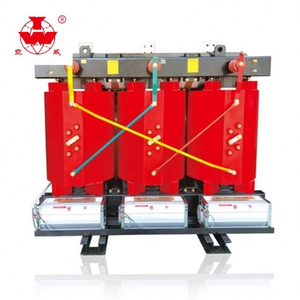
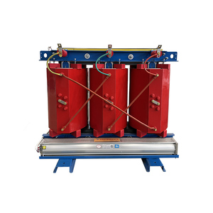
Flagship Copper Winding Transformers & Substations

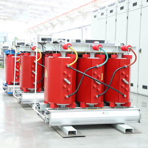
Engineered with 99.99% ETP electrolytic copper conductors, cold-rolled grain-oriented (CRGO) silicon steel cores, and certified under IEC 60076, IEEE C57, and ISO 9001 standards for long-term grid efficiency.

99.99%
ETP Electrolytic Copper Purity
30+ Years
Design Operating Service Life
<10 pC
Ultra-Low Partial Discharge
69 kV
Max Primary Voltage Rating
Metallurgical & Engineering Whitepaper

Why Copper Winding Outperforms Aluminum in Grid Infrastructure

An authoritative comparative analysis of physical, electrical, and thermal parameters governing transformer performance and 30-year lifecycle profitability.

When utility procurement officers and electrical consulting engineers evaluate power distribution equipment, conductor selection forms the single most critical structural decision. While aluminum conductors present a lower initial capital expenditure (CAPEX), 99.99% Electrolytic Tough Pitch (ETP) copper windings deliver overwhelmingly superior mechanical resilience, thermal dissipation dynamics, and reduced operational expenditure (OPEX) over a 30-to-40-year transformer lifecycle.

Engineering Metric / Physical Parameter Electrolytic Copper (ETP / OFC) Standard Aluminum Conductor Grid Performance Impact
Electrical Conductivity (% IACS) 100% – 101% IACS 61% IACS Copper requires 38% less conductor cross-section for equivalent current capacity.
Thermal Conductivity (W/m·K) 398 W/m·K 237 W/m·K Rapid dissipation of hot-spot heat, preventing dielectric paper cellulose degradation.
Tensile Yield Strength (MPa) 200 – 400 MPa 70 – 160 MPa Exceptional resistance to electrodynamic radial deformation during short-circuit faults.
Coefficient of Thermal Expansion ($10^{-6}/K$) 16.5 23.1 Minimal expansion/contraction stress on resin seals and turn-to-turn insulation.
Galvanic Oxidation & Connection Creep Negligible Oxide Layer Formation High Oxide Resistance & Cold Flow Eliminates high-resistance joint heating, bolt loosening, and terminal failure risks.
Volumetric Transformer Footprint Compact (1.0x Baseline) Large (~1.6x Oil/Core Volume) Dramatically reduces substation footprint, enclosure dimensions, and fluid volume.

Key Takeaway for B2B Purchasing Authorities:

The electrodynamic force experienced by a transformer winding during a short-circuit fault scales quadratically with current ($F \propto I^2$). Under massive fault conditions, aluminum coils are prone to mechanical yield deformation and radial buckling (telescoping). In contrast, copper's superior yield strength ensures structural stability, preserving grid continuity during severe external distribution faults.

Manufacturer Capabilities & Precision Testing

State-of-the-Art Factory Standards & QA Protocols

Our partner manufacturing plants leverage advanced European automation, clean-room winding facilities, and ISO/IEC 17025 accredited test bays to guarantee zero-defect production.

99.99% ETP Copper Rod Sourcing

We strictly utilize Oxygen-Free (OFC) and Electrolytic Tough Pitch (ETP) copper rods. Conductor strips undergo continuous up-casting, multi-pass cold drawing, and high-precision annealing for maximum flexibility and electrical conductivity.

⚙️

Automated Vertical Winding

Equipped with micro-processor tensioning control vertical and horizontal winding machines. Eliminates mechanical displacement, ensuring tight turn-to-turn spatial geometry and optimal radial voltage gradient distribution.

🔬

Vacuum Pressure Impregnation (VPI)

High-capacity Hedrich vacuum casting chambers and VPI systems ensure complete resin penetration into coil inter-layers, removing micro-cavities to achieve partial discharge thresholds below <10 pC.

🏭

Georg Laser Core-Cutting Lines

Core laminations are processed using imported Heinrich Georg CNC step-lap cutting lines. High-permeability CRGO silicon steel strips minimize core magnetic reluctance, achieving ultra-low no-load losses ($P_0$).

🛡️

ISO/IEC 17025 Accredited FAT Lab

Every transformer undergoes full Factory Acceptance Testing (FAT), including Lightning Impulse Withstand, Temperature Rise, Induced Overvoltage, Applied Voltage, Short-Circuit Withstand, and Dissolved Gas Analysis (DGA).

🌐

Global Utility Certification

Fully compliant with IEC 60076, IEEE C57, ANSI C57.12, CE, and ISO 9001/14001/45001 standards. Pre-qualified vendor for international power utilities, EPC contractors, renewable energy developers, and industrial parks.

Strategic Procurement Horizon

Future Technological & Market Procurement Trends

Key macro trends shaping the global market for copper winding transformers over the next decade.

Procurement Knowledge Base

Frequently Asked Questions (FAQ)

Expert technical answers addressing key technical, commercial, and quality assurance queries raised by utility buyers and project engineers.

Q1 Why should our project choose copper winding over aluminum winding for industrial step-down transformers?
Copper winding offers superior electrical conductivity (100% IACS vs 61% for aluminum), significantly higher thermal conductivity (398 W/m·K vs 237 W/m·K), and nearly 2.5 times higher tensile strength. This results in substantially lower load losses ($P_k$), a smaller physical footprint, reduced cooling oil/resin volume, and exceptional structural resistance against short-circuit electrodynamic forces, ensuring a reliable 30+ year lifespan.
Q2 How does copper conductor quality impact the Total Cost of Ownership (TCO)?
Although copper transformers have a 15–25% higher upfront purchase cost (CAPEX), their low internal resistance minimizes continuous $I^2R$ heat dissipation losses (OPEX) during daily grid operation. When calculating TCO over a 30-year lifecycle ($TCO = CAPEX + \sum Operating Loss Costs$), high-purity copper transformers typically achieve full capital payback within 3 to 5 years, yielding net financial savings thereafter.
Q3 What is the difference between Cast Resin Dry-Type and VPI Dry-Type Copper Transformers?
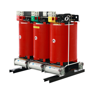
Cast Resin Dry-Type transformers have their copper coils fully encapsulated under deep vacuum in epoxy resin, providing absolute moisture protection, self-extinguishing fire resistance, and high structural rigidity—ideal for high-humidity, underground, or indoor environments. Vacuum Pressure Impregnated (VPI) transformers use polyester/silicone varnish dipping for ventilation, offering a cost-effective solution for dry, indoor commercial applications.
Q4 What key factory test documentation must be verified prior to equipment dispatch?
B2B buyers should request complete Factory Acceptance Test (FAT) dossiers compliant with IEC 60076-1. Essential reports include: (1) Winding Resistance Measurement, (2) Voltage Ratio & Vector Group Verification, (3) Short-Circuit Impedance & Load Loss Test, (4) No-Load Loss & Current Test, (5) Dielectric Separate-Source & Induced Overvoltage Test, and (6) Partial Discharge Test Report (<10 pC). Type test reports (Impulse & Short-Circuit Withstand) should be issued by accredited third-party labs like KEMA, ASTA, or VILAS.
Q5 Can your manufacturing facility customize vector groups, tap changers, and enclosures for specific grid codes?
Yes. Our partner factories provide complete OEM/ODM engineering customization. We accommodate primary voltages up to 69kV, non-standard secondary voltages, vector groups such as Dyn11, Ynd11, or Yyn0, Off-Circuit Tap Changers (OCTC) or On-Load Tap Changers (OLTC) with automatic voltage regulators (AVR), and enclosure ratings ranging from IP20 indoor cabinets to IP56 stainless steel outdoor housings.
Q6 What are the standard international lead times and export packaging protocols?
Standard production lead time ranges from 4 to 8 weeks depending on kVA capacity and testing requirements. All transformers are packed in seaworthy, heavy-duty wooden cases lined with vacuum-sealed moisture barrier foil, desiccants, and shock-impact indicators to ensure zero corrosion or structural vibration damage during ocean transport.
Partner with Leading Copper Winding Manufacturers

Need detailed CAD drawings, complete IEC type test reports, or an immediate competitive B2B quotation for your upcoming power grid or industrial project?