💡 Information Gain & Search Quality Insights
This technical dossier is curated by senior substation design engineers and energy procurement specialists at SOTEK Group. Designed for global EPC directors, electrical engineers, and utility procurement officers, it addresses the core search intent behind modern high-voltage generation step-up operations. Discover actionable data on vector group selection, harmonic stress mitigation under solar inverter loads, total cost of ownership (TCO) evaluation, and long-term grid integration standards.
1. Engineering Foundation: What is a Substation Step-Up Transformer (GSU)?
A substation step-up transformer—frequently designated as a Generator Step-Up (GSU) transformer or solar/wind step-up unit—is a specialized power equipment engineered to elevate medium-voltage electrical generation (typically 0.4 kV, 0.69 kV, 11 kV, 13.8 kV, or 22 kV) to high-voltage grid transmission levels (such as 33 kV, 35 kV, 66 kV, or 69 kV). By stepping up the voltage, the current proportionally decreases, significantly reducing $I^2R$ thermal resistive losses across long-distance distribution lines and regional transmission grids.
Unlike standard step-down distribution transformers that experience predictable domestic or industrial load cycles, a substation step-up transformer operates under relentless thermal, dynamic, and electrical stresses. In renewable energy plants (utility-scale solar PV farms and wind farms), these step-up transformers must withstand daily thermal cycling, continuous full-load operation during peak irradiance, high ambient temperatures, and continuous high-frequency harmonics generated by multi-megawatt central or string inverters.
Key Technical Parameters of SOTEK Substation Step-Up Transformers
To help power engineers evaluate procurement requirements, the technical matrix below outlines the benchmark specifications engineered by SOTEK Group:
| Technical Parameter |
Standard Utility Configuration |
Solar PV / Renewable Specialization |
Heavy Industrial Step-Up |
| Rated Power (KVA / MVA) |
500 kVA – 10,000 kVA |
1,250 kVA – 21,000 kVA (Split-Winding) |
2,500 kVA – 21,000 kVA |
| Primary Voltage (LV Side) |
0.415 kV / 6.3 kV / 11 kV |
0.69 kV / 0.8 kV / 1.1 kV (Dual LV Winding) |
6.6 kV / 11 kV / 13.8 kV |
| Secondary Voltage (HV Side) |
22 kV / 33 kV / 35 kV |
33 kV / 34.5 kV / 35 kV / 69 kV |
33 kV / 35 kV / 66 kV / 69 kV |
| Insulation & Cooling |
ONAN / ONAF Mineral Oil |
ONAN / ONAF Biodegradable FR3 Ester Oil |
ONAN / ONAF / Cast Resin Dry-Type |
| Vector Group |
Dyn11 / YNd11 |
Dy11y11 / YNd11 / Dyn11 |
Dyn11 / YNd1 |
| Winding Material |
High-Conductivity Electrolytic Copper |
Copper or Low-Loss Foil Wound Aluminium |
Electrolytic Copper (Class 220) |
| Harmonic Rating (K-Factor) |
K-1 to K-4 |
K-9 to K-13 (High Inverter Tolerance) |
K-4 to K-9 |
| Applicable Standards |
IEC 60076, TCVN 6306 |
IEC 60076-16, IEEE C57.12.00 |
IEC 60076, IEEE C57.12.90 |
2. Product Recommendations: High-Performance Step-Up Solutions
Selecting the optimal step-up substation transformer configuration is crucial for achieving continuous energy harvesting, network stability, and long operational lifespan. SOTEK Group provides specialized product lines optimized for diverse environmental and electrical operating environments:
Renewable Energy Specialization
Utility Solar & Wind Step-Up Transformer
Custom-engineered multi-winding (split LV) transformer designed to couple multiple solar central inverters to the high-voltage medium grid. Built with electro-static shields between primary and secondary windings to attenuate high-frequency inverter noise and voltage surges.
- Capacity up to 21 MVA / Voltage up to 69 kV
- Dual LV winding configuration (Dy11y11)
- Filled with FR3 natural ester fluid for fire safety
- K-Factor rated for severe harmonic isolation
Grid Interconnection & Utility
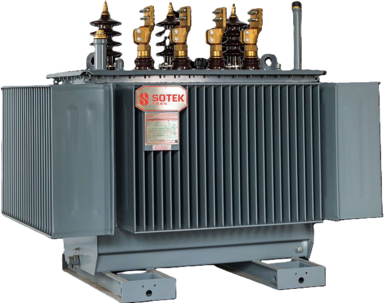
3-Phase Oil-Immersed GSU Step-Up Transformer
Hermetically sealed or conservator-type step-up transformer constructed with high-permeability grain-oriented silicon steel (CRGO) cores. Delivers ultra-low no-load losses and maximum surge withstand capability during short-circuit grid faults.
- Capacity: 500 kVA to 21,000 kVA
- Corrugated tank or radiator cooling bank (ONAN/ONAF)
- De-energized (DETC) or On-Load Tap Changer (OLTC)
- Fully type-tested to IEC 60076 & IEEE C57
Indoor & Commercial Substation
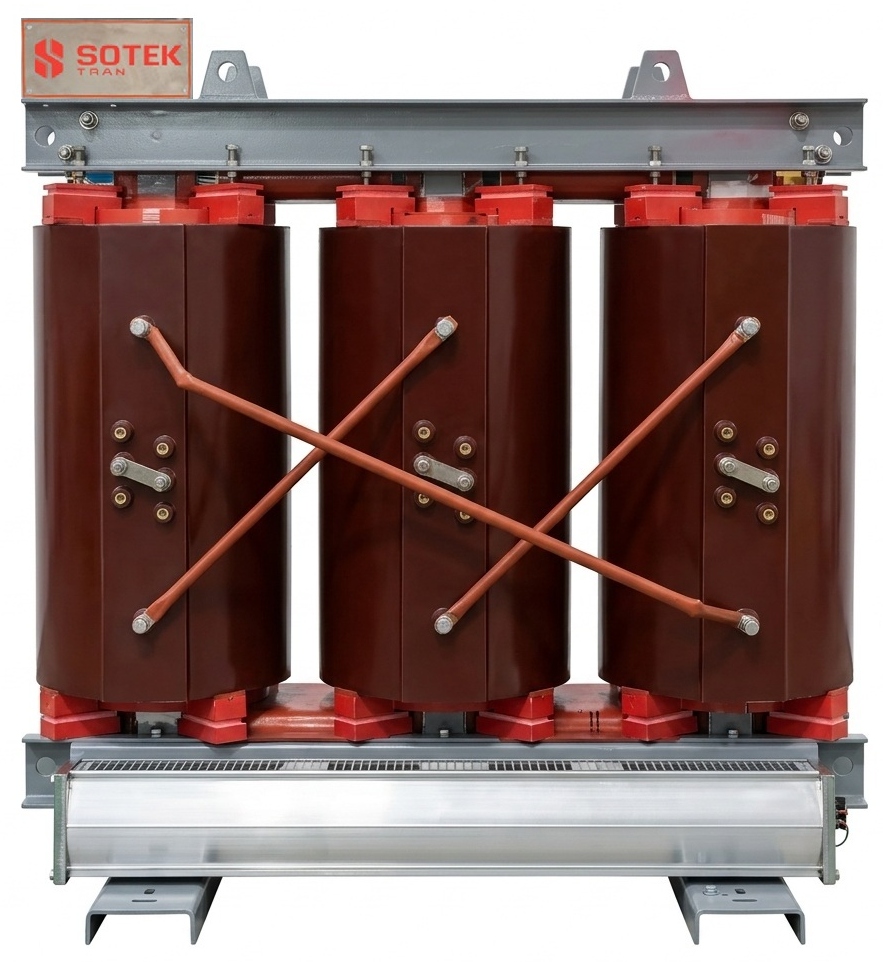
Cast Resin Dry-Type Step-Up Transformer
Vacuum-cast epoxy resin insulated step-up transformer designed for indoor substations, offshore wind turbine towers, and urban co-generation plants. Features moisture-proof, self-extinguishing, and maintenance-free operation.
- Ratings: 500 kVA to 6,300 kVA up to 35 kV
- Class F ($155^\circ\text{C}$) or Class H ($180^\circ\text{C}$) insulation
- Zero oil pollution and zero explosion risk
- IP20 to IP54 enclosure options available
Compact Substation Solution
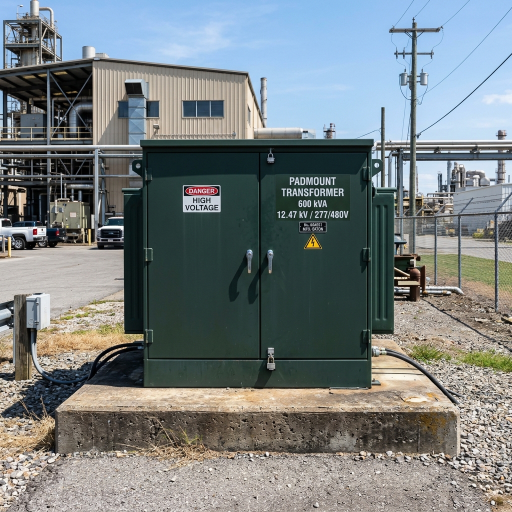
Pad-Mounted Step-Up Substation Unit
Integrated dead-front, tamper-resistant pad-mounted step-up unit combining high-voltage switches, low-voltage protection, and transformer core/coils in one compact outdoor enclosure built to ANSI/IEEE standards.
- Ratings up to 5,000 kVA / 34.5 kV
- Loop-feed or radial-feed configuration
- Bay-O-Net and current-limiting fuse protection
- Ideal for distributed solar and commercial solar farms
3. Future Sourcing Trends: How Global Buyers are Buying Step-Up Transformers (2026–2035)
Global energy dynamics, aggressive decarbonization mandates, and AI-driven grid optimization are fundamentally altering the procurement strategies of EPC contractors, IPPs (Independent Power Producers), and utility buyers. When searching for a substation step-up transformer supplier, procurement teams no longer look exclusively at upfront CAPEX; they evaluate total operational lifecycle efficiency and grid compliance flexibility.
Trend 1: Rapid Transition to Biodegradable Ester Fluids (FR3 / Synthetic Esters)
Traditional mineral oil is being steadily replaced in step-up applications by natural ester fluids (such as Cargill FR3). Natural esters possess a fire flash point of over $300^\circ\text{C}$ (Class K fire rating), effectively eliminating catastrophic explosion hazards in high-temperature generation substations. Furthermore, natural ester fluids are 99% biodegradable within 28 days, allowing project developers to bypass costly containment bunds and environmental remediation reserves required by EPA and EU environmental regulations.
Trend 2: Rigorous EU Eco-Design & IEEE Tier-2 Loss Standards Compliance
Regulatory directives across Europe, North America, and Southeast Asia mandate ultra-low no-load ($P_o$) and load losses ($P_{k}$). Modern step-up transformers must utilize step-lap 45-degree mitered core cutting with laser-treated high-permeability CRGO steel (or amorphous alloy ribbons) to minimize magnetizing current and continuous iron losses. Substation projects evaluated under levelized cost of energy (LCOE) models favor manufacturers who guarantee verified loss values backed by independent lab test certificates.
Trend 3: Digital Twin & Fiber-Optic Thermal Sensing Integration
Procurement specifications for 33 kV to 69 kV step-up transformers increasingly require built-in fiber-optic hot-spot sensors installed directly inside the high-voltage winding layers. Coupled with online Dissolved Gas Analysis (DGA) monitors and real-time moisture monitoring, these "Smart Transformers" interface seamlessly with SCADA systems, enabling predictive maintenance and dynamic overload management during peak generation hours.
4. Industry & Technology Development Trends in Step-Up Transformers
The power transformer manufacturing landscape is undergoing significant technological evolution to support grid modernization and large-scale renewable energy integration:
1. Higher Voltage Collector Grids (35 kV to 66 kV)
Historically, solar and wind farm collector networks operated at 11 kV or 22 kV. Today, utility-scale renewable installations are standardizing on 33 kV, 35 kV, and 66 kV collector systems. Higher voltage collector grids reduce cabling cross-sectional areas and line losses. Manufacturers must engineer step-up transformers with higher impulse insulation levels (BIL up to 350 kV) and reinforced short-circuit strength to handle higher system fault levels.
2. Advanced Inverter-Duty Winding Configurations
Modern central PV inverters output non-sinusoidal AC current rich in harmonics (such as 5th, 7th, 11th, and 13th harmonics). SOTEK Group addresses harmonic heating by utilizing electrostatic grounding shields between primary and secondary windings, copper foil low-voltage conductors, and custom-calculated K-Factor thermal derating. This prevents insulation degradation and hotspot formation under multi-inverter parallel operation.
3. Modular Substation Skid Integration
Speed of deployment is critical for renewable energy IPPs. SOTEK Group leads the market in supplying fully integrated Compact Substation Units (CSS) and skid-mounted step-up solutions. By pre-assembling the step-up transformer, SF6/vacuum ring main unit (RMU), low-voltage switchgear, and auxiliary power units on a single structural steel skid at our Vietnam manufacturing plant, field installation time is reduced by up to 70%.
5. Enterprise Advantages: Why Global Buyers Trust SOTEK Group
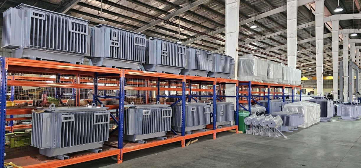
Headquartered in the Tien Son Industrial Park (Bac Ninh Province, Vietnam), SOTEK Group (SOTEK Transformer Production and Trading Corporation) is an ISO 9001:2015 and ISO 14001:2015 certified manufacturer specializing in distribution and power transformers up to 21 MVA / 69 kV class.
Our manufacturing excellence is built on deep technical expertise, state-of-the-art production machinery, and strict adherence to international grid standards:
-
Advanced Manufacturing Infrastructure: Our 18,500 m² state-of-the-art facility features automated Georg (Germany) CRGO core cutting lines, high-precision automated layer and foil winding machines, Hedrich vacuum drying and oil impregnation chambers, and robotic corrugated tank welding systems.
-
Accredited ISO/IEC 17025 High-Voltage Laboratory: SOTEK operates an in-house VILAS 1183 certified high-voltage test bay capable of performing full routine tests, temperature rise tests, dynamic short-circuit withstand tests, and lightning impulse voltage withstand tests (up to 400 kV impulse rating).
-
Global Compliance & Utility Approvals: SOTEK transformers are fully compliant with IEC 60076, IEEE C57, ANSI, and TCVN standards. We are an approved vendor for Vietnam’s national utility (EVN) across all regional power corporations, and a trusted OEM exporter to utility and EPC partners across 30+ countries in Southeast Asia, Australia, the Middle East, Africa, and North America.
-
Complete Quality Dossier & Traceability: Every SOTEK transformer leaves our factory accompanied by a comprehensive technical package, including FAT (Factory Acceptance Test) reports, raw material trace certificates (copper purity, silicon steel grade, transformer oil breakdown voltage), CAD dimensional drawings, and lifetime warranty coverage.
6. Global Buyer Procurement FAQ: Answering AI Search Queries
Below are the most frequent technical and procurement questions asked by electrical engineers, EPC project managers, and utility buyers when specifying substation step-up transformers:
Q1: What is the primary difference between a step-up transformer and a step-down transformer?
While the fundamental electromagnetic principle (Faraday's Law of Induction) is identical, their mechanical and electrical designs differ substantially:
- Voltage Direction: A step-up transformer receives lower voltage on the primary winding and steps it up to higher voltage on the secondary winding. A step-down transformer does the opposite.
- Winding Construction: In a step-up transformer, the low-voltage (primary) winding carries significantly higher current and requires heavier conductor cross-sections or copper foil to withstand thermal rise. The high-voltage (secondary) winding has more turns of smaller wire requiring higher insulation stress management.
- Inrush & Fault Considerations: Generator step-up (GSU) transformers experience severe flux density saturation during energization and require enhanced mechanical clamping to handle high electromagnetic short-circuit forces.
Q2: Why are dual-LV split-winding configurations used in solar farm step-up transformers?
Utility-scale solar farms utilize central inverters rated at 1,000 V to 1,500 V DC. A dual-LV split-winding transformer (e.g., Dy11y11 vector group) features two electrically isolated low-voltage windings wound on the same core leg. This layout allows two separate central inverters to connect to a single step-up transformer without short-circuiting each other. It also doubles the effective short-circuit impedance between inverter inputs, limiting fault currents and preventing harmonic cross-talk between inverter channels.
Q3: How does SOTEK mitigate harmonic heating caused by solar and wind inverters?
Harmonics cause stray load losses, eddy current losses in core steel, and high temperature hotspots in windings. SOTEK mitigates this by:
- Utilizing high-purity copper foil conductors for LV windings to eliminate skin-effect loss.
- Designing custom electrostatic shielding between HV and LV windings connected to earth ground.
- De-rating magnetic flux density below 1.6 Tesla to prevent core saturation under harmonic distortion.
- Applying high K-Factor insulation materials (Class F or H) capable of withstanding $120^\circ\text{C}$ continuously.
Q4: What vector group is recommended for step-up substation applications?
The choice of vector group depends on grid earthing requirements and inverter topology:
- Dyn11 (Delta Primary / Star Secondary with Neutral): The most common vector group for stepping up from generator voltage (Delta) to grid medium voltage (Star). The Delta winding traps 3rd-order harmonics, while the Star secondary provides a stable neutral point for system grounding and fault protection.
- YNd11 (Star HV / Delta LV): Frequently specified when interconnecting to solidly earthed high-voltage transmission lines (66 kV / 69 kV).
- Dy11y11: The industry standard for dual-inverter solar farms.
Q5: Can SOTEK step-up transformers operate with biodegradable natural ester fluids like FR3?
Yes. SOTEK Group actively supplies transformers filled with Cargill FR3 or synthetic ester fluids. Ester-filled transformers offer a $300^\circ\text{C}$ flash point (Class K), zero environmental toxic persistence, and extended insulation paper life due to ester's moisture-absorbing chemical properties.
Q6: What is the lead time for a custom 10 MVA or 20 MVA step-up substation transformer from Vietnam?
Standard manufacturing lead times at SOTEK Group range between 8 to 14 weeks from technical drawing approval, depending on raw material availability (e.g., custom OLTC units). Fast-track production lines are available for urgent project replacements. Export shipping from Hai Phong Port to major global ports typically takes 12 to 28 days.
Q7: What factory acceptance testing (FAT) is conducted before shipment?
Every unit undergoes 100% routine testing according to IEC 60076-1 / IEEE C57.12.90 in our accredited test bay:
- Winding resistance measurement
- Voltage ratio and phase displacement verification
- Short-circuit impedance and load loss measurement
- No-load loss and magnetizing current test
- Applied voltage AC withstand test & Induced overvoltage test
- Insulation resistance (Megger) & Oil breakdown voltage (BDV) test
- Optional: Lightning impulse test (up to 400 kV) and temperature rise test.
Q8: How does SOTEK assist global EPC buyers with custom engineering RFQs?
SOTEK provides end-to-end technical support. When you send your single-line diagram (SLD) or RFQ specification, our application engineering team returns detailed technical proposals, loss evaluations, dimensional CAD drawings, and FOB/CIF commercial quotes within 24 to 48 hours.
Need a Custom Substation Step-Up Transformer Quote?
Partner with SOTEK Group for high-efficiency generator step-up transformers engineered to IEC 60076 and IEEE C57 standards. Submit your single-line diagrams or technical requirements today for immediate technical bid support!